 |
|||
|
|
|||
|
Page Title:
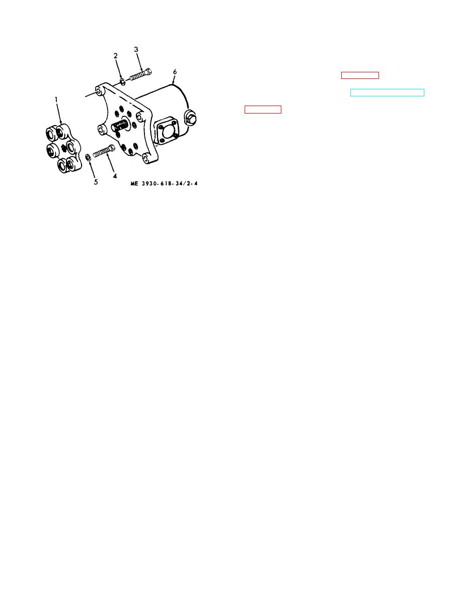
Figure 2-4. Hydraulic pump removal and installation. |
|
||
| ||||||||||
|
|
 2-11. Hydraulic Lift Assembly
a. Description. The hydraulic lift assembly consists
of hydraulic cylinder, carriage and inner and outer masts
with wear plate in the sliding channels to provide
maximum ease of movement.
b. Removal. Refer to figure 2-5 and remove as
follows:
(1) Remove lift forks (TM 10-3930-618-20).
(2) Detach tilt cylinders from mast. brackets
(3) Attach chain hoist to lifting eyes on the
back of outer mast and raise mast assembly enough to
take weight off pivot pins.
(4) Remove lock wires from capscrews.
Remove capscrews, lockwashers, and remove pivot
pins.
(5) Lift mast assembly free of truck.
1 Coupling
4 Screw
2 Lockwasher
5 Lockwasher
3 Screw
6 Pump
Figure 2-4. Hydraulic pump removal and installation.
2-10
|
|
Privacy Statement - Press Release - Copyright Information. - Contact Us |
