 |
|||
|
|
|||
|
Page Title:
Section VI. MAINTENANCE OF THE FUEL SYSTEM |
|
||
| ||||||||||
|
|
 f. Advance the flywheel until the ignition timing
j. Start the engine and using the idle adjustment
line on the flywheel is aligned with the reference line
screw, lower the low idle speed to 400 RPM.
on the flywheel housing. This line is TDC (top dead
k. Direct the timing light at the timing hole in the
center).
flywheel housing and rotate the distributor to set the
g. If necessary, mark the flywheel and housing with
timing to TDC (0 ), then tighten the distribution ad-
white chalk or paint.
vance screw.
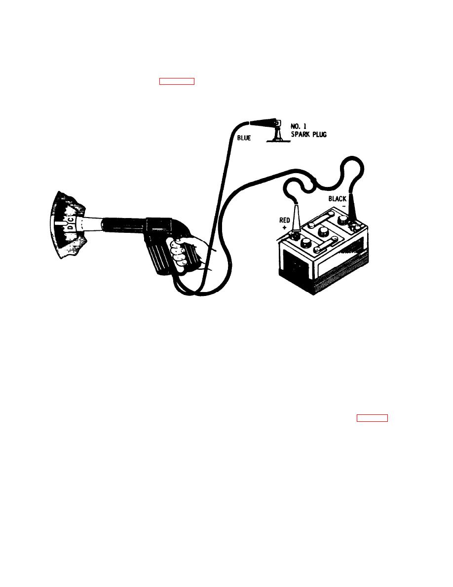
h. Connect a timing light as shown in figure 2-9.
I. Increase the low idle speed to 450 to 500 RPM.
i. Connect the hot lead of a tachometer to the
positive lead on the coil and connect remaining lead to
ground.
ME 3930-618-20/2-9
Figure 2-9. Timing light connections.
m. With the timing light, again check flywheel
ment of the flywheel timing mark. If the spark advance
timing and note whether IGN TDC line on flywheel
is functioning properly IGN TDC mark on the fly-
has moved away from reference line on flywheel
wheel will move counterclockwise away from the
reference line on the flywheel housing. As the engine
housing.
decelerates the IGN TDC on the flywheel will line up
n. After timing is correctly adjusted, accelerate
with reference line on flywheel housings.
the engine rapidly a few times and observe the move-
Section VI. MAINTENANCE OF THE FUEL SYSTEM
a. Removal. Loosen the hose clamp, unscrew the
2-15. General
wingnut, and lift out the filter assembly (fig. 2-10).
The fuel system is comprised of an 14.5 gallon capac-
b. Disassembly. Remove the cover and lift out the
ity tank, diaphragm-type fuel pump, single-venturi
oil cup.
updraft carburetor, centrifugal governor, and con-
c. Cleaning.
necting lines. A bowl type fuel filter is included as an
(1) Pour out the old oil from the oil cup and
integral part of the fuel system.
scrape away accumulated dirt from the bottom of the
2-16. Carburetor Air Cleaner
oil cup.
(2) Clean the cover, oil cup, and base assembly
CAUTION
inside and outside with SD.
Never remove the air cleaner while the engine
(3) Refill the oil cup (rapacity 1/2 pt) with engine
is naming.
oil of grade and weight presently used in the engine.
Do not run the engine unless the air cleaner
d. Assembly. Reverse procedures in b above.
is in place.
2-16
|
|
Privacy Statement - Press Release - Copyright Information. - Contact Us |
