 |
|||
|
|
|||
|
|
|||
| ||||||||||
|
|
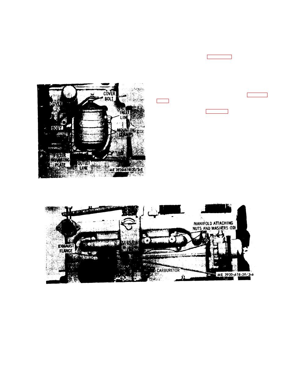 2-11. Manifold Assembly
(2) Inspect the body and cover for breaks or
cracks.
a. General. The exhaust and intake manifold is a
(3) Inspect fittings and hardware for stripped or
one-piece casting: stud-mounted to the cylinder head.
damaged threads. Replace damaged parts.
The carburetor is attached to the intake section and
d. Assembly. Reverse procedures in b above.
the exhaust pipe is attached to the exhaust outlet
e. Installation. Reverse procedures in a above.
flange. Unless physically damaged, the manifold will
f . Filter and Element Replacement. The filter element
require little service.
should be replaced at each engine oil change. Wipe the
b. Removal. Refer to figure 2-6 and remove the
cover area clean and proceed as directed in b above.
manifold as follows:
Discard the cover gasket. The element and cover gasket
(1) Remove engine side panels, seat, seat deck,
are contained in a kit.
and air cleaner.
(2) Remove the carburetor air hose. rocker arm
cover breather line and exhaust pipe.
(3) Disconnect choke control, accelerator rod.
and governor control rod from the carburetor (para
(4) Close the fuel supply valve at the fuel tank.
Remove the carburetor (para 2-17).
(5) Remove the nuts and washers attaching the
manifold to the studs and remove the manifold.
(6) Remove the retainers and gaskets from the
manifold ports.
c. Cleaning and Inspection.
(1) Remove carbon deposits using PD-680.
(2) Check for cracks and warpage. To check for
warpage, lay a straight-edge across the manifold ports
Replace damaged parts.
d. Installation.
(1) Reverse procedures in b above.
(2) Use new gaskets.
(3) Tighten attaching nuts to 32-35 foot-pounds
Figure 2-5. Engine oil filter, installed view.
of torque.
Figure 2-6. Manifold assembly, installed view.
2-13
|
|
Privacy Statement - Press Release - Copyright Information. - Contact Us |
