 |
|||
|
|
|||
|
Page Title:
TABLE 6-1. WEAR LIMITS AND CLEARANCES |
|
||
| ||||||||||
|
|
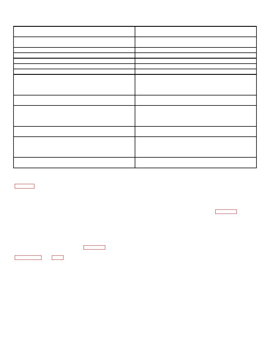 TABLE 6-1. WEAR LIMITS AND CLEARANCES
Drive axle - axle shaft
0.003 inch maximum, total
run out
indicator reading
Drive axle - differential
0.000 to 0.003 inch loose
preload
Adapter - input gear backlash
0.006 to 0.008 inch
Motor brake shoes
1/16 inch minimum thickness
Service brake shoes
1/16 inch minimum thickness
Steering gear - lash adjuster
0.002 inch end play maximum
Travel motor - brushes
3/4 inch minimum length
Travel motor - armature
4.375 inches minimum diameter,
commutator
16 microinch rms surface
roughness, 3/64 inch deep by
0.030 inch wide undercutting
Hydraulic pump motor
-1/2 inch minimum length
brushes
Hydraulic pump motor -
2.375 inches minimum diameter,
armature
16 microinch rms surface
roughness, 3/64 inch deep by
0.025 inch wide undercutting
Power steering motor -
1/2 inch minimum length
brushes
Power steering motor -
1.500 inches minimum diameter,
armature
16 microinch rms surface
roughness, 3/64 inch deep by
0.020 inch wide undercutting
Tires
3/4 inch minimum thickness
(approximately)
observed, consult the corresponding or most closely
6-14.
TESTING SCR'S AND DIODES. It is not
associated symptom listed in the left hand column of
necessary to remove these components from the
chassis for testing. Proceed as follows:
note the listing of the probable causes, and conduct the
corrective actions given.
1.
For power diodes (1REC, 2REC and 3REC),
6-12.
TECHNIQUES.
remove anode cable connection and connect continuity
test light in diode circuit as shown in figure 6-1a. A good
diode will light test light when connection is made in one
6-13.
These techniques are primarily used for
direction and not light when connection is reversed. If
locating defects in the electric power control circuit, and
test light lights in both connections, diode is defective
stress the approach of using continuity checks
and must be replaced.
(ohmmeter or test light) to determine the condition of a
component part. When checking electrical or electronic
2.
For SCR'S (1SCR and 2SCR), remove
components, and unless otherwise stated, always
cathode cable and white gate lead. Connect test light as
disconnect the battery connector. Table 6-3 provides a
shown in figure 6-lb.
Next, reverse test light
list of the test equipment required in servicing. Consult
connections. In each test, test light should not light. If
light comes on, SCR is shorted and must be replaced.
connections.
6-3
|
|
Privacy Statement - Press Release - Copyright Information. - Contact Us |
