 |
|||
|
|
|||
|
Page Title:
Drive Axle, Wheel Cylinder and Brake Shoes |
|
||
| ||||||||||
|
|
 TM 10-3930-611-35
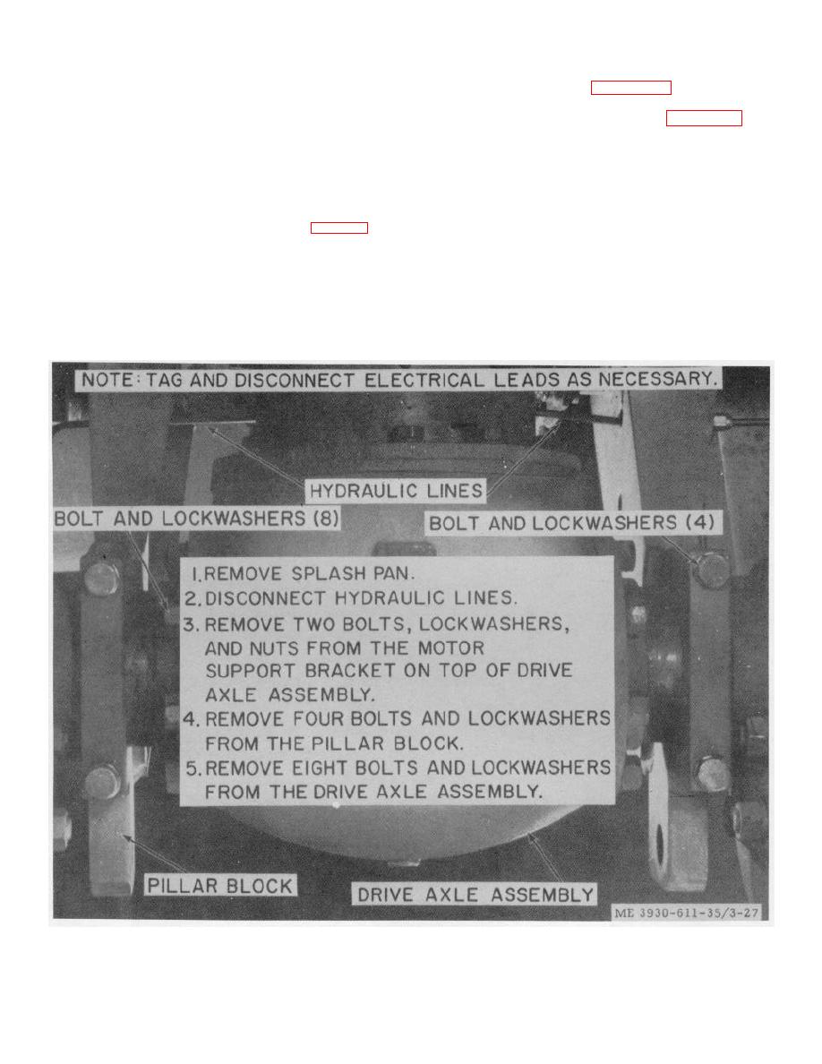
(2) Refer to figure 3-27 and remove the
the brake master cylinder.
e. Installation.
drive axle assembly.
Install the brake master
cylinder (TM 10-3930-611-12).
f.
disassemble the drive axle, wheel cylinder, and brake
shoe assembly.
system (TM 10-3930-611-12).
c. Cleaning, Inspection and Repair.
g. Push Rod Adjustment.
(1) Wipe the brake shoe with a clean, dry
(1) Ensure that the foot pedal is in the
cloth. Clean all other parts with dry cleaning solvent
fully upward position.
(Federal Specification P-D-680) and dry thoroughly.
(2) Observe the piston travel through the
(2) Inspect brake lining for glaze, grease
filler hole. Adjust the cylinder push rod (fig. 3-28) to
or oil soaked condition, and wear. Inspect wheel
approximately 1/16 inch free travel without any
bearings for pitting and spindles for out-of-straightness.
movement of the piston.
Inspect wheel cylinder for leaking oil. Inspect tires for
3-23. Drive Axle, Wheel Cylinder and Brake Shoes
wear. Inspect all parts for breaks, cracks, loose or
a. Removal.
missing mounting hardware, or other defects.
(1) Remove the drive wheels (TM 10-
3930-611--12).
Figure 3-27. Drive axle assembly, removal and installation.
3-33
|
|
Privacy Statement - Press Release - Copyright Information. - Contact Us |
