 |
|||
|
|
|||
|
Page Title:
Section VII. REPAIR OF HYDRAULIC PUMP |
|
||
| ||||||||||
|
|
 TM 10-3930-609-35
i. Rotate wormshaft until ball nut is about in center
o. Install pitman arm on splined end of pitman
of travel.
shaft gear with washer and nut.
j. Place side cover gasket on housing.
3-43. Installation and Adjustment of Steering Gear
k. Insert pitman shaft gear into housing, ensuring
that center tooth engages center tooth space of ball nut.
I. Secure side cover to housing with screws and
b. After installation, adjust steering gear (TM 10-
washers, ensuring that there is some lash between
3930-609-12).
pitman shaft gear and ball nut as screws are tightened.
m. Mount bracket on housing with screw, washer
and nut.
n. Fill housing with lubricant (LO 10-3930-609-12).
Section VII. REPAIR OF HYDRAULIC PUMP
3-45. Removal of Hydraulic Pump
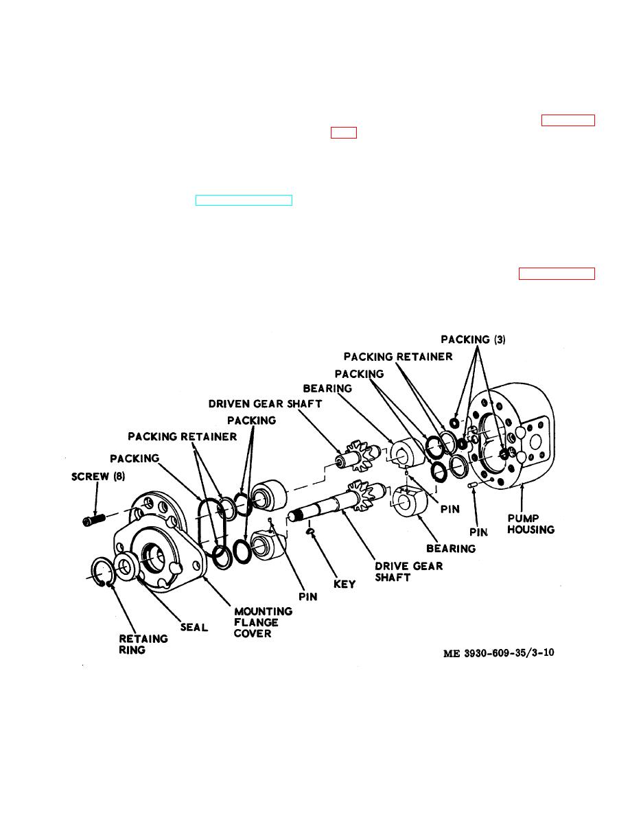
3-44. Description of Hydraulic Pump
Removal of the dydraulic motor is required for repair as
The hydraulic pump is driven by the electric pump motor
described in these instructions. Refer to paragraph 2-21
and provides hydraulic fluid pressure for extending the
for removal procedure.
tilt cylinders and the hoist cylinder. The pump is a
positive displacement type having a rated capacity of
3.400 gallons per minute at 1,200 rpm and 1,000 psi.
Figure 3-10. Hydraulic pump, exploded view.
3-17
|
|
Privacy Statement - Press Release - Copyright Information. - Contact Us |
