 |
|||
|
|
|||
|
Page Title:
Section III. RADIO INTERFERENCE SUPPRESSION |
|
||
| ||||||||||
|
|
 TM 10-3930-609-35
for voltage drop to zero after the battery switch is closed
2-9. Test of Fl Filter and SCR Firing Circuits.
is much less or greater than one second, adjust 1A
TIME trimpot to obtain approximately one second timer
Both the filter and SCR firing circuits contained in filter
action. A finer adjustment may be made later, if
necessary, during a checkout of truck performance.
Disconnect battery and filter leads as required for the
tests.
Note
The timer controls the delay in the
a. Test of 5 REC Firing Circuit. Disconnect lead to
pick up of relay 1A, which cuts out
terminal 7 of F1. With ohmmeter set to RX100 range,
the SCR control system and applies
connect positive lead to terminal 8 and negative lead to
full battery voltage to the travel
terminal 7. The resistance reading should be between
motor for full-speed operation. This
1,700 and 2,100 ohms. With the leads reversed an
occurs when the accelerating control
infinity reading should be obtained.
is fully depressed to close switch
b. Test of 2 REC Firing Circuit. Disconnect lead to
ASA2. If the timer closes relay 1A
terminal 5 of F1. With ohmmeter set to RXi00 range,
too early, truck operation will be
connect positive lead to terminal 6 and negative lead to
jerky; if timer closes 1A too late,
terminal 5. The resistance reading should be between
truck operation will be sluggish.
1,170 and 1,430 ohms. With the leads reversed an
infinity reading should be obtained.
(4) If the timer does not operate at all, or
cannot be adjusted properly with the 1A TIME trimpot,
terminal 4 of F1. With ohmmeter set to RX100 range,
replace Card 1.
connect positive lead to terminal 6 and negative lead to
terminal 4. The resistance reading should be between
2,050 and 2,750 ohms. With the leads reversed an
infinity reading should be obtained.
d. Allowing for Meter and Reading Errors. If any
reading in the three preceding tests on F1 is definitely
outside the specified values, filter F1 should be
replaced.
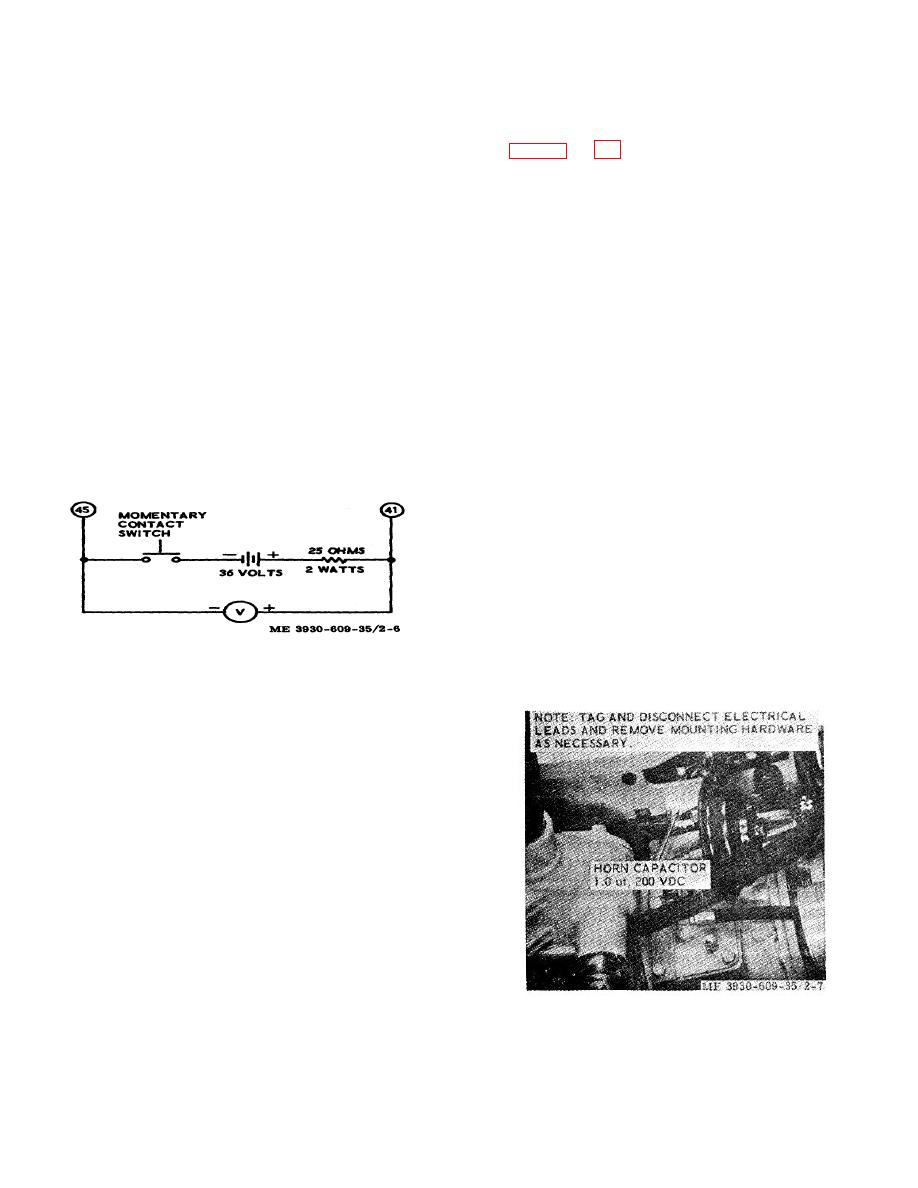
Figure 2-6. Test circuit for times section of card 1.
Section III. RADIO INTERFERENCE SUPPRESSION
2-10. General
Refer to TM 11-483 for definitions, purposes, source and
methods used to obtain proper radio suppression.
2-11.
Testing of Radio Interference Suppression
Components
If the radio suppression component is suspected of
being defective, proceed as follows:
a. Disconnect leads 13A-1 and 84 from screw-type
terminals on component.
b. Take out two screws, flatwashers, and
lockwashers which secure component to master cylinder
support to remove component.
c. Check component on a capacitor tester for leak
and short. Replace component if defective.
Figure 2-7. Interference, suppre8sion component,
removal and installation.
2-11
|
|
Privacy Statement - Press Release - Copyright Information. - Contact Us |
