 |
|||
|
|
|||
|
|
|||
| ||||||||||
|
|
 TM 10-3930-609-12
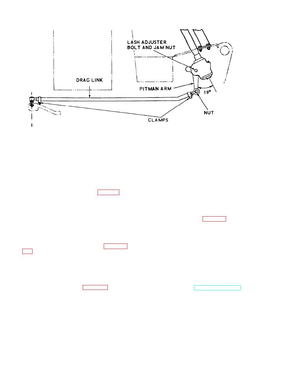
ME 3930-609-12/3-23
Figure 3-23. Steering adjustment.
c. If measurements obtained in a and b above
(3) Draw wheel from steering axle spindle.
differ by 1/16 inch, adjust as below until wheels
Because of manufacturing tolerances the cone
are parallel to within 1/16 inch as measured in
and rollers of the inboard bearing may remain
a and b above.
with spindle. If so, it can easily be removed.
Avoid damaging oil seal, if possible, when re-
moving wheel.
3-68. Wheel Alinement Adjustment
b. Installation. Reverse procedures in a above,
a. Loosen (but do not remove) screws and
tightening wheel nut snug, then backing it off
nuts from all tie rod end clamps (fig. 3-24).
not more than 1/6 turn, and install cotterpin.
b. Turn each tie rod an equal number of turns
in the direction necessary to change toe-in as re-
3-70. Rear Wheel Bearings
quired.
a. Removal.
Note. Each tie rod has right hand threads at one
( 1) Remove rear wheels (para 3-69a).
end, left hand threads at the other, so adjustment can
(2) Pull bearings from bore of wheel. A
be made to change effective length without dismounting
tie rod.
slip hammer bearing puller may be used to pull
bearings from wheel if they stick in bore.
c. When adjustment has been completed,
(3) Remove retaining rings which position
tighten tie rod clamp screws and nuts and re-
bearings.
check wheel alinement measurement (para 3-
b. Service.
(1) Clean bearings with SD and dry
thoroughly.
3-69. Rear Wheels
(2) Inspect cups and rollers for wear or
a. Removal.
failure. Inspect cone and roller assemblies for
(1) Lower forks fully and tilt mast back.
roughness when rotated.
Raise rear of truck until wheels clear floor.
(3) If bearings are serviceable, repack with
(2) Remove hub cap (fig. 3-25), and re-
grease in accordance with LO 10-3930-609-12,
move cotterpin, nut, and washer from bore of
using a bearing packing device, if available.
wheel.
c. Installation. Reverse procedures in a above.
3-32
|
|
Privacy Statement - Press Release - Copyright Information. - Contact Us |
