 |
|||
|
|
|||
|
|
|||
| ||||||||||
|
|
 TM 10-3930-609-12
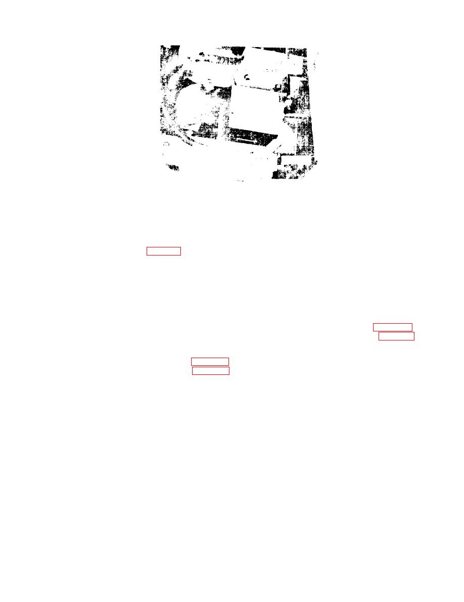
Figure 3-18. Accelerator master assembly.
Section Xl. HYDRAULIC SYSTEM
(8) Remove screws, nuts and lockwashers
3-57. General
securing bracket and switch actuator hinge; re-
The hydraulic system (fig. 3-19) consists of a
move bracket and switch actuator hinge.
pump and drive motor, control valves, hoist and
b. Installation. Reverse procedure in a above,
tilt cylinders, filters, hoses and lines for the op-
adjusting position of sleeves on connecting rods
eration of the tilt and lift functions of the fork
until control valve actuation is proper, then
lift truck. This section provides information use-
secure with setscrews.
ful in the repair of the hydraulic system. When
ever hydraulic components are disconnected or
3-59. Tilt Cylinders
removed, operate the tilt and hoist control valves
a. Removal.
several times after installation to purge air from
(1) Remove truck floor plate (para 3-18).
the hydraulic system.
(2) Tag and disconnect hoses (fig. 3-21)
3-58. Control Valve levers and Linkage
from tilt cylinders. Cap hoses and plug ports in
a. Removal.
cylinders to exclude dirt.
( 1) Remove valve cover plate (para 3-21).
(3) Support mast so it will not suddenly
(2) Remove retaining rings (fig. 3-20)
tilt on removal of tilt cylinders.
securing connecting rods to hoist and tilt levers.
Warning: If not supported the mast will
(3) Pull out cotterpin securing rod in
fall forward when the tilt cylinders are discon-
bracket and pull out rod to release hoist and
nected.
tilt levers.
(4) Remove screws and lockwashers secur-
(4) Remove screws attaching shafts to
ing bracket to truck and remove bracket.
brackets on truck frame and on uprights.
(5) Remove cotterpins and clevis pins
(5) Pull or drive shafts from cylinder ends.
securing clevis and connecting rods to control
Be careful not to let cylinder fall as shafts are
valve. If valve actuation is proper, note position
removed.
of sleeves and connecting rod clevises before dis-
b. Installation.
assembling them from the connecting rods.
(6) Compress spring, turn disc to release
(1) Position tilt cylinder (back end) in U
pin and remove disc, spring and pin from
shaped bracket on truck frame.
bracket.
(2) Aline bracket holes and cylinder end
(7) Remove screws securing spacer clips;
hole. Insert shaft through bracket and cylinder
remove spacer clips.
end hole. Secure shaft with screw.
3-27
|
|
Privacy Statement - Press Release - Copyright Information. - Contact Us |
