 |
|||
|
|
|||
|
|
|||
| ||||||||||
|
|
 UPRIGHTS
primary and secondary rods are forced out of the
cylinder shell. The guide and crosshead assembly,
being attached to the top of the secondary rod, moves
up. At this time the carriage, which travels twice as fast
as the crosshead, is free-lifting.
The carriage will free-lift until the top lug on the back of
the crosshead engages and rotates the latch in the box.
of the crosshead contacts the upper crossmember of the
inner upright. (Fig. 25) Since the left latch is now free
to rotate, it does so while the inner upright rises. The
right latch will rotate until it rests against and locks the
left latch around the top lug on the crosshead.
Figure 25.
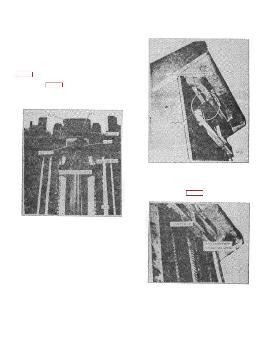
As the inner upright is extended, the cylinder guide
makes contact with the upper crossmember on the
intermediate upright. (Fig. 26)
Figure 24.
The second stage begins after the inner upright is free to
rise. At this time, the crosshead is latched to the inner
upright, and the intermediate upright is latched to the
outer. The inner upright is free to rise. The secondary
rod in the cylinder will move out of the primary rod when
the primary rod reaches the end of its travel.
Figure 26.
At the same time the lug on the adapter plate engages
and rotates the front latch on the intermediate upright,
unlocking the rear latch. With the rear latch free to
B-183
|
|
Privacy Statement - Press Release - Copyright Information. - Contact Us |
