 |
|||
|
|
|||
|
|
|||
| ||||||||||
|
|
 UPRIGHTS
3. Disconnect the load chains from the anchors on
the hoist cylinders and pull them out the bottom of the
upright assembly.
4. Attach a sling and a hoist to the cylinder, being
careful not to bend the anchors.
5. Remove the lowering control valve from the
bottom of the cylinder. Separate the crosshead from the
cylinder. Hoist the cylinder out of the upright assembly.
Figure 11.
9. Remove the snap ring, shims and load rollers
from the bottom of the inner uprights (Fig. 12) and from
the top of the outer. (Fig. 13)
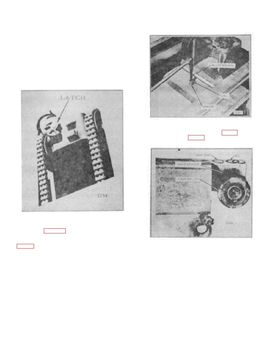
Figure 10.
6. Rotate the front latch clockwise, as indicated by
the arrows in Figure 10, and at the same time, pull the
inner upright out of the top of the outer until the lug on
the outer can be removed. Remove the lug and spacer.
Figure 12.
NOTE:
7. Remove the pad and bracket assembly from the
To aid in assembling and adjusting, identify the
outer upright.
shims as they are removed.
8. Push the inner upright into the outer until the
NOTE:
lower crossmembers contact each other.
At this stage, all rollers may be removed
without removing other units from the
uprights. The strip bearings can be removed
by prying the inner upright up enough to allow
removal of the bearings.
B-174
|
|
Privacy Statement - Press Release - Copyright Information. - Contact Us |