 |
|||
|
|
|||
|
|
|||
| ||||||||||
|
|
 UPRIGHTS
inch) check for too much side play in the latch
shaft. If little side play is noticeable, the carriage
position with respect to the inner upright must be
changed.
IMPORTANT: When placing the lug closer to or farther
away from the latch, all the shim packs of the load
rollers are altered. In altering the packs, remember the
following: (1) When shims are removed from one side
of a load roller, they must be placed on the other side of
the same roller. (2) Alter the shim packs of all the load
rollers on a given side of the carriage the same; that is,
if a .030 inch shim was removed from the outer side and
placed on the inner side of the lower roller on the right
vertical member, alter the pack of each of the two upper
rollers on the right vertical member by transposing a
.030 shim. (3) Whenever shims are removed from the
outer side of and placed on the inner side of the rollers
on the right vertical member, the opposite must be done
to shim packs on the left vertical member and vice
versa.
UPRIGHTS
A. GENERAL
Latches and latch lugs (socket head capscrews) are
utilized to maintain the proper operating sequence of the
upright assembly, by securing the inner upright to the
outer and releasing it at the proper time. (Figs. 6 and
7).
There are three latches and two lugs, which make up the
latching mechanism. The latches are located at the top
of the inner upright. One of the lugs is located on the
back of the upper crossmember of the carriage. The
other is in front of the upper crossmember of the outer
upright.
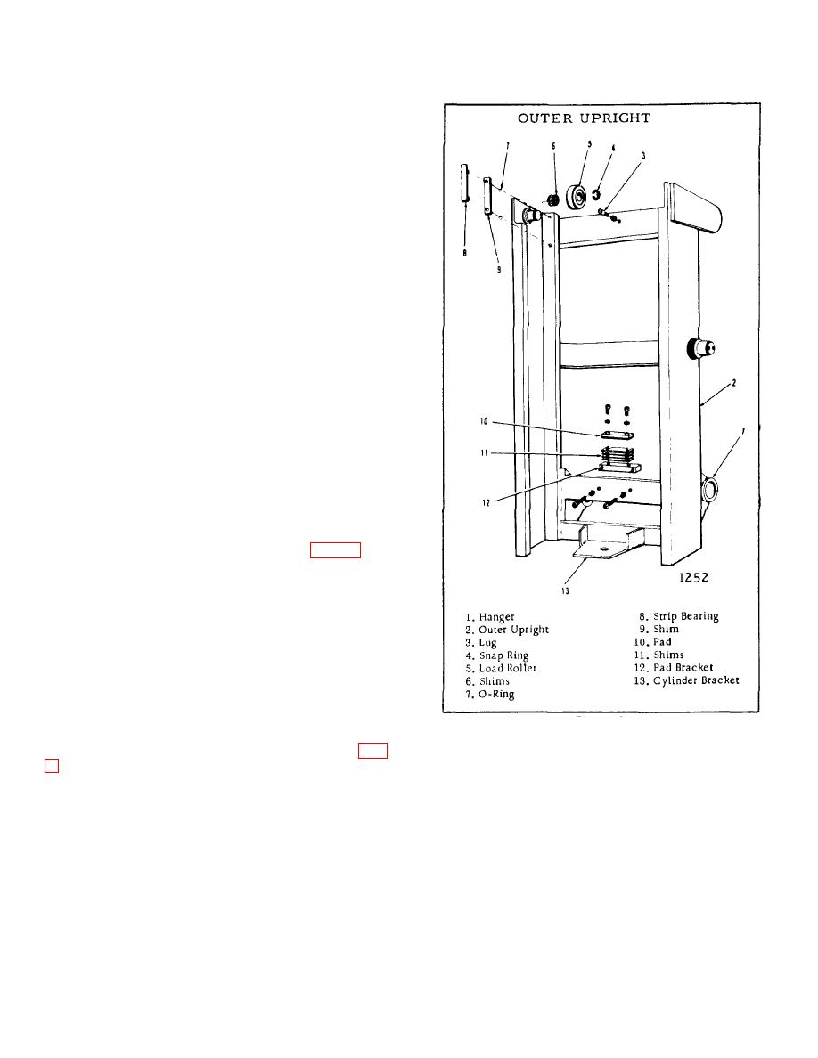
Attached to the top of the hoist cylinder is a crosshead
and cylinder guide assembly. The guide, which is shim-
Figure 6.
adjusted, slides in two guide rails. One guide rail is
welded to the back of each outer upright channel. (Fig.
top of each outer upright channel. The other two are at
the bottom of the inner channels. The rollers are
equipped with sealed ball bearings, lubricated for life
Taking the load and side thrust imposed on the uprights
and replaced as an assembly.
are four canted load rollers. One roller is located at the
B-171
|
|
Privacy Statement - Press Release - Copyright Information. - Contact Us |
