 |
|||
|
|
|||
|
|
|||
| ||||||||||
|
|
 BRAKES
3. Make sure the rubber boot is in position on the
Using a spare push rod, work the piston through its
push rod and master cylinder. This is important,
entire stroke until fluid is forced from the fitting end of
otherwise, dirt and water can enter the master cylinder
the cylinder. After fluid begins to flow from the fitting,
bore, causing premature failure.
continue to work the piston until at least 1/4 pint of fluid
is expelled from the fitting hole.
Throughout the
purging, keep sufficient fluid in the reservoir to prevent
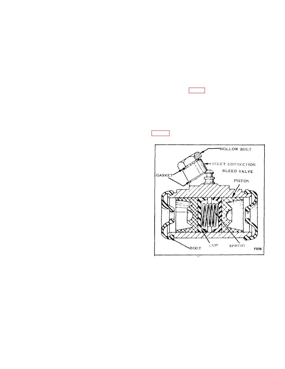
WHEEL CYLINDER
air from being pumped into the cylinder.
A. GENERAL
There are two cylinders on each truck. One in each
3. Cap fitting end of cylinder. Then fill reservoir.
brake assembly. (Fig. 6) Their purpose is to change
hydraulic flow and pressure to the mechanical
4. Place a new gasket on the filler cap and screw
equivalents.
the cap into the reservoir.
The wheel cylinder houses two opposed pistons, two
rubber cups and a spring. On the outside of the cylinder
F. INSTALLATION
is a bleed valve, hydraulic line fitting and two rubber
boots.
1. Install master cylinder using the reverse of
removal procedure. To prevent an aerated system,
tighten the line to master cylinder fitting while
depressing the brake pedal.
2. Adjust the master cylinder.
G. ADJUSTMENT
1. Adjust the adjustable link with pedal back until
cylinder push rod contacts the piston in the master
cylinder.
2. Check the pedal free-travel. Check inching.
NOTE: If the pedal linkage does not provide proper
clearance between the master cyl-, inder piston and the
linkage with brakes released, the piston cannot return to
full "off" position and the primary cup lip will seal the
cylinder by-pass port. Then the compensating feature of
the master cylinder cannot function and surplus fluid
Figure 13.
cannot return from the brake lines. Brakes will drag
after several applications if the by-pass port is blocked.
Although not utilizing the same drilled passages, the line
fitting and bleeder valve are in communication with the
cylinder bore in this manner.
B-135
|
|
Privacy Statement - Press Release - Copyright Information. - Contact Us |
