 |
|||
|
|
|||
|
|
|||
| ||||||||||
|
|
 DRIVE AXLE
addition of shims between the
4. If backlash is not between .008 and .011 inch,
transmission
and
differential
adjust as necessary.
mounting flanges.
Reference to
moving gear toward or away from
NOTE:
pinion refers to transferring 'shims
To decrease backlash, remove shims
between the R and L axle flanges.
from between the pinion side of the
differential housing and the axle
1. Check adjustments at drive side of bevel gear
housing flange, and place them on
tooth.
the ring gear side.
To increase
clearance, remove the shims from
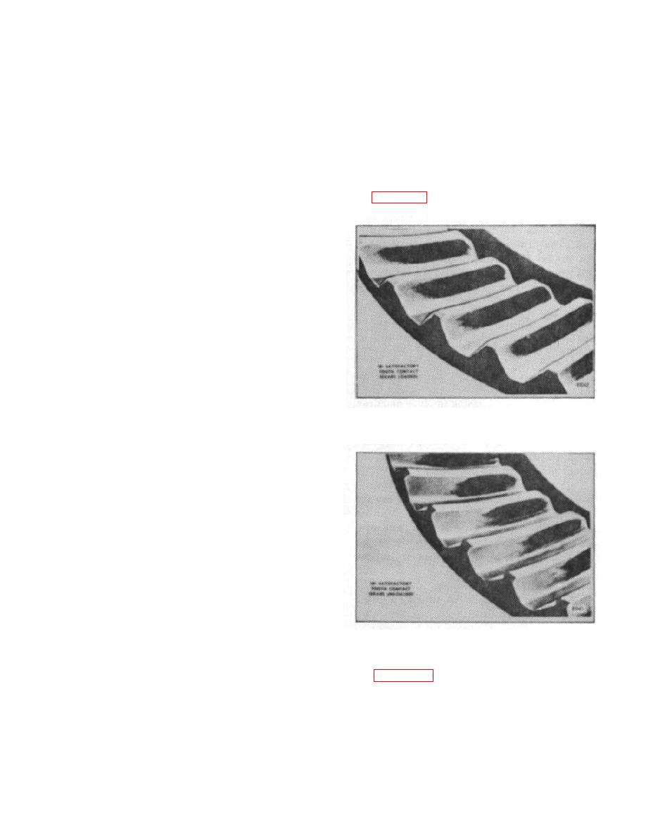
2. Figures 18 and 19 show correct tooth contact.
the ring gear side of the housing and
place them on the pinion side.
CAUTION:
It is important to place the shims
removed from one side of the
housing on the opposite side.
Otherwise the bearing preload will be
affected.
5. Rotate ring gear and check backlash at several
points on the ring gear. Separate drive axle from the
transmission when the backlash is within specifications.
6. Apply a light coating of white lead to several of
the pinion teeth, on both the drive and coast sides.
Figure 18.
Secure the differential assembly to the transmission
case using new gaskets with the same thickness as the
old gaskets. Tighten down four capscrews spaced
evenly around the flange and rotate the pinion shaft one
full turn in both directions. At the same time, note the
amount of backlash between the ring gear and pinion.
Remove the capscrews and lift the differential assembly
from the transmission.
7. Compare the pattern with those shown in
paragraph D. Tooth Contact.
D. TOOTH CONTACT
NOTE:
The following figures show the
results of too little or too much
pinion depth as determined from the
Figure 19.
impression of the tooth bearing on
the white lead.
3. Figure 20 shows short contact at heel. To
correct, move gear toward pinion. Then move pinion
NOTE:
away from gear to again secure correct backlash.
Reference to moving pinion toward
or away from ring gear in above
description refers to the removal or
B-126
|
|
Privacy Statement - Press Release - Copyright Information. - Contact Us |
