 |
|||
|
|
|||
|
|
|||
| ||||||||||
|
|
 DRIVE AXLE
to replace either the pinion or ring gear of the hypoid
2. Lubricate differential case inner walls and all
set, the entire gear set should be replaced.
component parts with axle lubricant. Position thrust
washer and side gear in gear and case half assembly.
Place spider with pinions and thrust washers in position.
6. Inspect
the
differential
assembly
for
the
Then install remaining side gear and thrust washer.
following:
3. Align mating marks, position component case
a. Pitted, scored or worn thrust surfaces of
half and draw assembly together with four capscrews
differential case halves, thrust washers,
equally spaced. Check assembly for free rotation of
spider trunnions, and differential gears.
differential gears and correct if necessary. Install
Thrust washers must be replaced in sets.
remaining capscrews.
The use of combination of used and new
washers will result in premature failure.
4. If bearings are to be replaced, press them
squarely and firmly on differential case halves.
b. Wear or damage to the differential pinions
and side gear teeth.
5. Assemble remaining parts in the reverse order
in which they were removed, making the necessary
7. Inspect axle shaft for twisted or cracked splines
adjustments as assembly progresses.
and other signs of impeding failure.
E. ASSEMBLY
6. Heat the pinion bearing retaining collar enough
to drop into place next to the pinion bearing.
1. If ring gear was removed from case, rivet the
gear to the case half with new rivets. Rivets should not
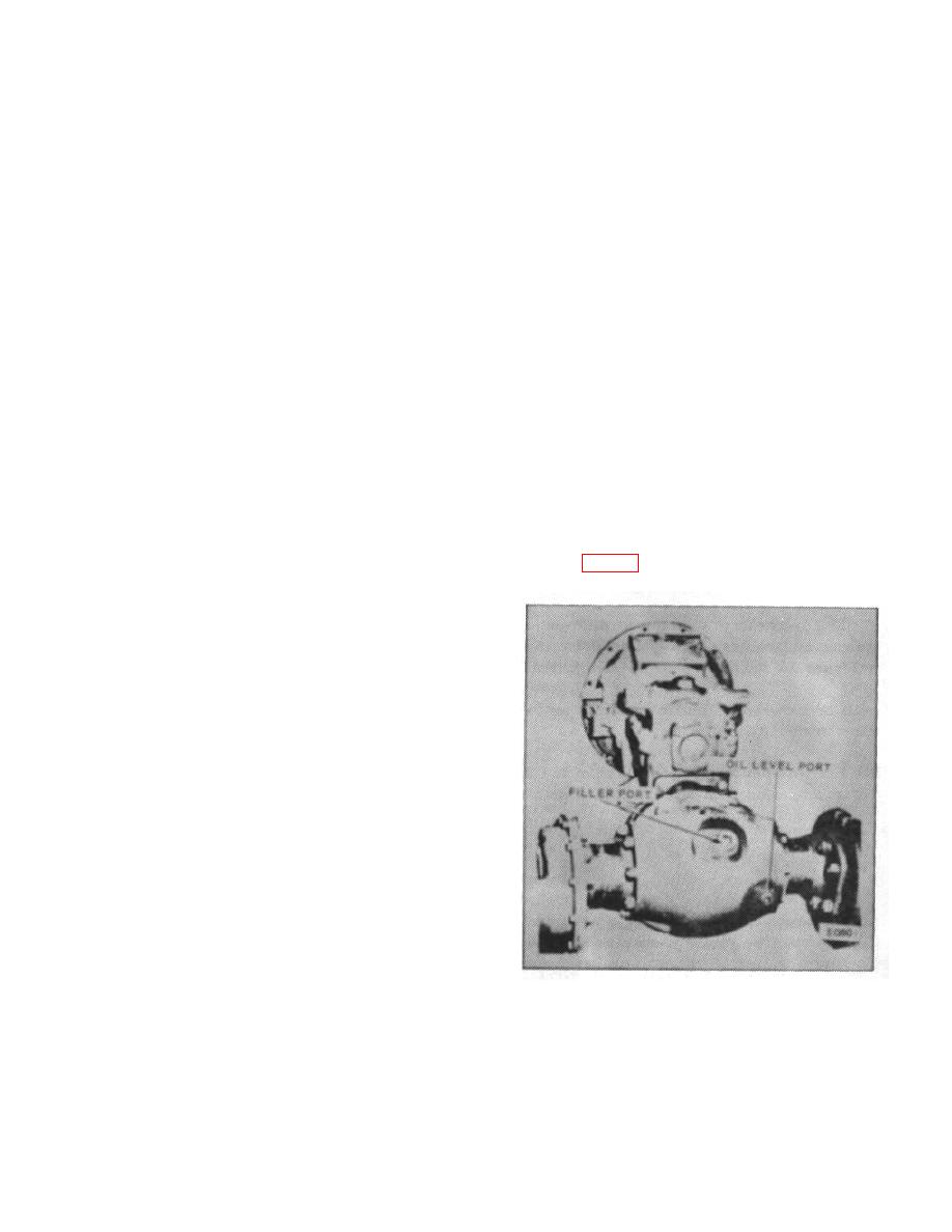
7. Remove the plugs from the oil filler port and oil
be heated. They are upset cold. When the correct rivet
level port. (Fig. 16) Add oil
is used, the head being formed will be at least 1/8 inch
larger in diameter than the rivet. The head will then be
approximately the same height as the preformed head.
CAUTION:
Excess pressure will cause distortion
of the case holes and result in gear
run-out.
NOTE:
Tonnage required for squeezing cold
rivets is charted below.
These
pressures are approximated for
annealed steel rivets and pressure
can be adjusted to suit individual
working conditions.
Diameter of Rivet
Tonnage Required
7/16"
22
1/2"
30
9/16"
36
5/8"
45
Figure 16.
B-124
|
|
Privacy Statement - Press Release - Copyright Information. - Contact Us |
