 |
|||
|
|
|||
|
|
|||
| ||||||||||
|
|
 ELECTRICAL
e.
If the receiver does not operate
1.
One new fuel tank sending unit. If there is
correctly, then check the wire lead to the
any question about the new tank unit being correct, then
receiver unit.
hook it up in series with a receiver unit known to be
satisfactory. Operate tank unit by hand and see if
(1) Attach one end of the ten foot
receive unit reads zero with tank unit float in bottom
length of wire to the terminal of the
position.
receiver unit to which the wire lead is
attached.
2.
Two 5 foot lengths of insulated wire
equipped with clip terminals at each end. These long
(2) Ground the other end of the
lengths will permit individuals making the check to sit in
long lead and turn the ignition switch.
seat of truck and observe gauge being checked. To
check, proceed as follows:
(3) If the gauge operates now and
did not operate with the regular wire
a.
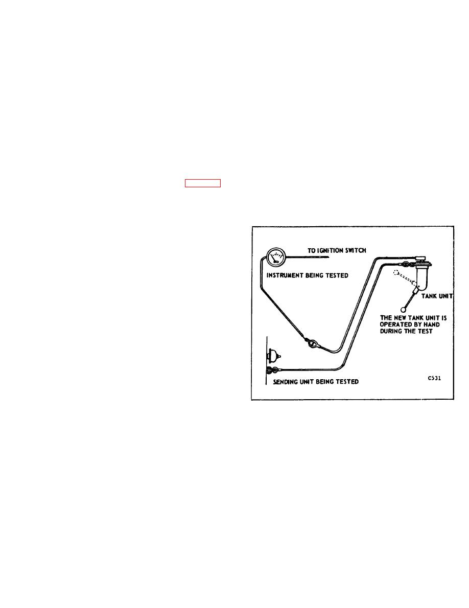
Disconnect sender unit being checked
connection, the wiring is at fault.
and hook in tank unit as shown in Figure 44.
Turn on ignition switch and operate float rod
f.
If wiring is satisfactory, then replace
of tank unit by hand.
receiver unit and check again with tank unit.
b.
With float of tank unit at bottom
position, receiver unit should register at
bottom mark on dial.
c.
Move float rod up to top position, then
the needle of the unit being checked should
move to top mark on dial.
NOTE: Allow one minute for receiver
to come to rest.
d.
If the receiver unit operates correctly,
it is then known the sending unit or wiring is
at fault.
NOTE: Do not attempt to repair the
sender unit. When installing a new
engine unit, do not use thread
compound on unit threads, as this
will increase electrical resistance of
unit and cause faulty operation.
Figure 44.
B-87
|
|
Privacy Statement - Press Release - Copyright Information. - Contact Us |
