 |
|||
|
|
|||
|
|
|||
| ||||||||||
|
|
 ELECTRICAL
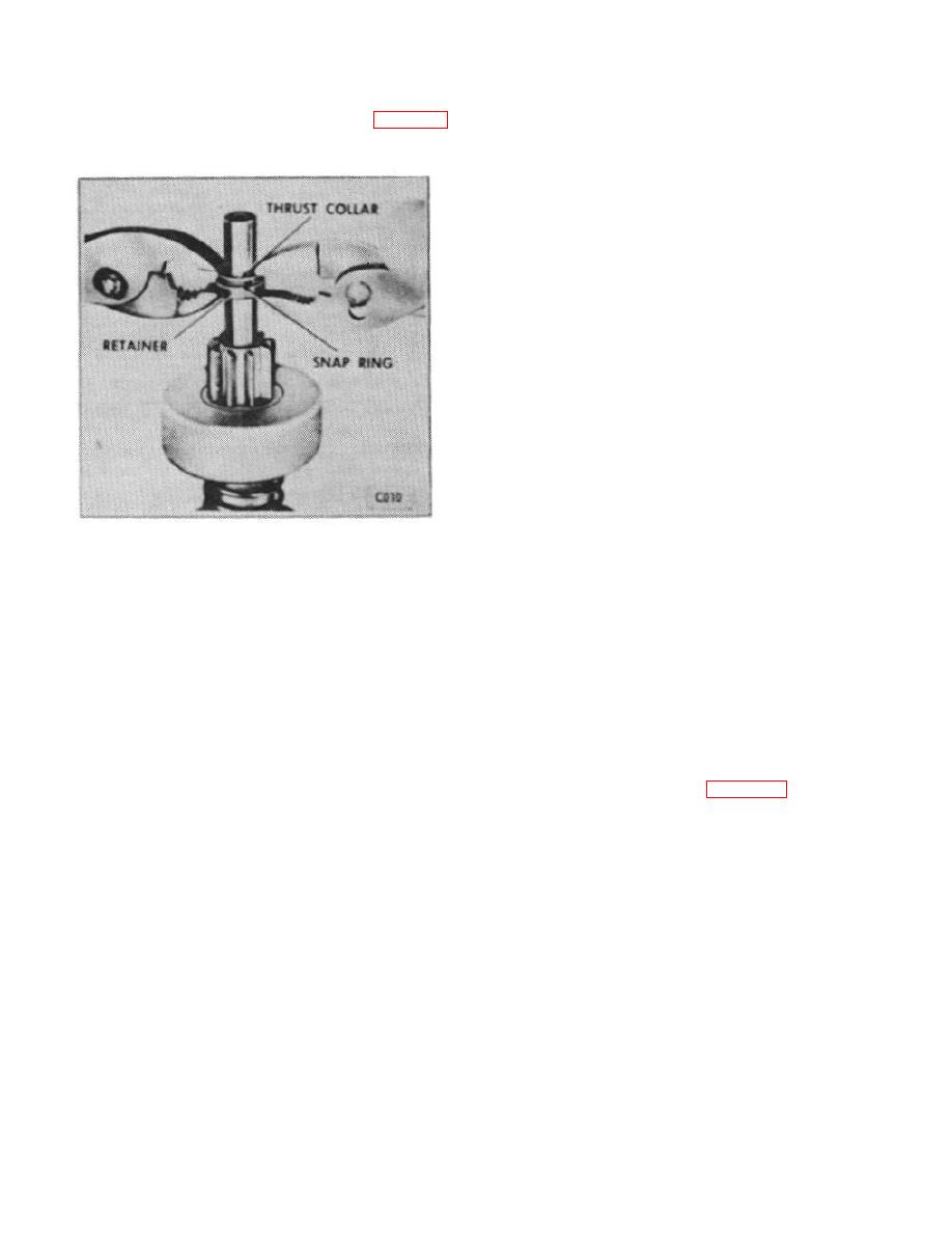
f. Position retained and collar next to snap ring,
then use two pairs of pliers as shown in Figure 38
8. Attach field coil connector to solenoid terminal
with screw and lockwasher.
to force retainer over snap ring.
9. Check drive pinion clearance as directed later
under " rive Pinion Clearance."
D
10. If testing equipment is available, No Load and
Torque Tests may be made to determine if starter is up
to specifications.
H. DRIVE PINION CLEARANCE
1. The drive pinion clearance should be checked
whenever the starter has been overhauled. There is no
means of adjusting the pinion clearance. If clearance is
not within specified limits, it may indicate excessive
wear of the solenoid linkage or shift lever yoke lugs.
Clearance between the end of the pinion and the pinion
stop, with the pinion in cranking position, is shown in
Specification Listing.
2. To check clearance, connect a voltage source of
approximately 6 volts (three battery cells in series or a
6-volt battery) between the solenoid switch terminal (S)
Figure 38.
and ground.
4. Install thrust washer over end of armature shaft,
CAUTION: Do not connect the voltage source to
then install armature and overrunning clutch assembly
ignition coil terminal (R) of the solenoid. Do not
in drive end housing, tilting armature as necessary to
use a 12-volt battery instead of the 6 volts specified
make lugs on shift lever yoke engage collar on
as this will cause the motor to operate. As a further
overrunning clutch.
precaution to prevent motoring, connect a heavy
jumper lead from the solenoid motor terminal to
5. Assemble solenoid and return spring to drive
ground.
housing, with solenoid plunger inserted into solenoid
case, and secure with two screws and lock washers.
3. After energizing the solenoid with the clutch
shifted forward, push the pinion back as far as possible
6. Apply sealing compound to extended portion of
to take up any movement, and check the clearance with
solenoid case flange contacted by field frame. Make
a feeler gauge as shown in Figure 39. If not within
sure all brush holders, springs, and brushes are installed
specifications, disassemble and replace worn parts in
in field frame and all leads are securely connected.
solenoid and shift lever linkage.
7. Place field frame over armature shaft, pulling
I. TESTING
brushes out over commutator, and engage dowel pin in
field frame in hole in drive housing. Install commutator
If the brushes. brush spring tension, and commutator
end frame over armature shaft, then install through-bolts
through commutator end frame and thread into tapped
holes in drive housing. Tighten through-bolts firmly.
B-79
|
|
Privacy Statement - Press Release - Copyright Information. - Contact Us |
