 |
|||
|
|
|||
|
|
|||
| ||||||||||
|
|
 FUEL
E. ASSEMBLY (Fig. 3)
1. Place choke plate in air intake assembly with
poppet valve toward gasket surface.
2. Insert shaft and lever assembly.
3. With choke plate closed, align hole in shaft with
hole in plate.
4. Center the choke plate in a closed position and
tighten screw. Do not attempt to rivet threaded end of
screw.
5. Install vacuum cylinder assembly and new fibre
washer in air intake assembly.
6. Install new fuel valve seat and fibre washer.
7. Install fuel valve needle in seat, followed by
float and float axle. Insert tapered end of float axle (27)
into float bracket on side opposite slot and push through
the other side. Press float axle into slotted side until the
axle is centered in bracket.
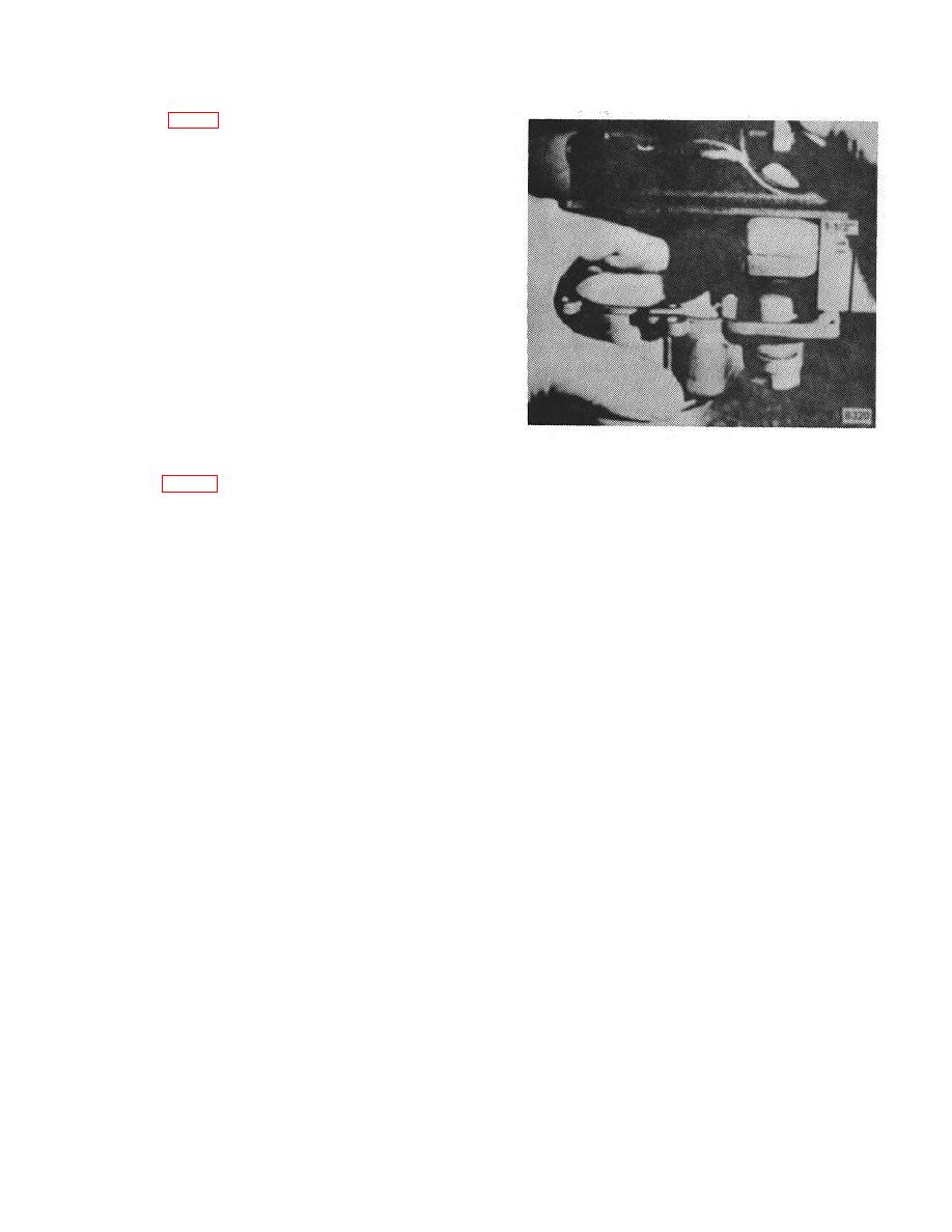
Figure 4.
8. Set float level to the standard setting using a 6"
depth gauge. (Fig. 4) Do not bend, twist or apply
11. Install main jet and fibre washer in bottom of
pressure on the float body. With air intake assembly in
fuel bowl and seat firmly.
inverted position, as viewed from the free end of float,
12. Install power jet valve assembly.
float body should be centered at right-angle to bowl
13. Install main discharge jet into passage in
cover. The float setting is measured from the machined
outside bottom of fuel bowl.
surface of air intake assembly to top side of float body
14. Install lower plug and fibre washer in passage
at highest point. The standard setting for this carburetor
on outside bottom of fuel bowl, using a 1/2" wrench.
is 1-1/2 inches. To change the distance between float
15. Install well vent jet in top surface of fuel bowl
and the machined surface of air intake, bend float lever
assembly.
close to the float body.
16. If the fit of the throttle shaft is sloppy in the
9. Drive each of the lead plugs into channels until
throttle body and it is desired to use the same throttle
plug heads are flush with surface of the casting. Only
body for re-assembly of the carburetor, then it is
one or two light hammer blows are required to seal lead
absolutely necessary to install throttle shaft bushings. A
plug in channel. Avoid driving plugs too deep, otherwise
poor fitting throttle shaft will upset engine idle, cause
plug may block off other fuel passages.
incorrect throttle plate location in relation to the idle
10. Install idle jet in top surface of fuel bowl (no
discharge port, and allows air and dirt to be admitted
gasket is used).
into the throttle body around the shaft.
B-41
|
|
Privacy Statement - Press Release - Copyright Information. - Contact Us |