 |
|||
|
|
|||
|
Page Title:
Section XIII. BOOM ASSEMBLY, INSTRUMENT PANEL AND FRAME |
|
||
| ||||||||||
|
|
 Section XIII. BOOM ASSEMBLY, INSTRUMENT PANEL AND FRAME
b. Removal.
3-80. General
(1) Remove clutch oil pressure gage, engine
The boom assembly consists mainly of two parts,
oil pressure gage, brake oil pressure gage (Model
the outer boom, which mounts to the frame, and the
RTL-10), converter temperature gage, water
i n n e r s l i d e . The various hydraulic cylinders are
temperature gage, brake pressure gage valve
d e s c r i b e d in Section XII. The instrument panel
( M o d e l RTL-10), ammeter, hourmeter, ignition
contains all the instruments, gages, and switches for
switch, start button, bank indicator (Model RTL
the proper operation of the forklift. The frame is
10-1), flood light and headlight switches, and panel
constructed of heavy material to enable the forklift
lights (TM 10-3930-243-12).
to be operated over rough terrain with a minimum
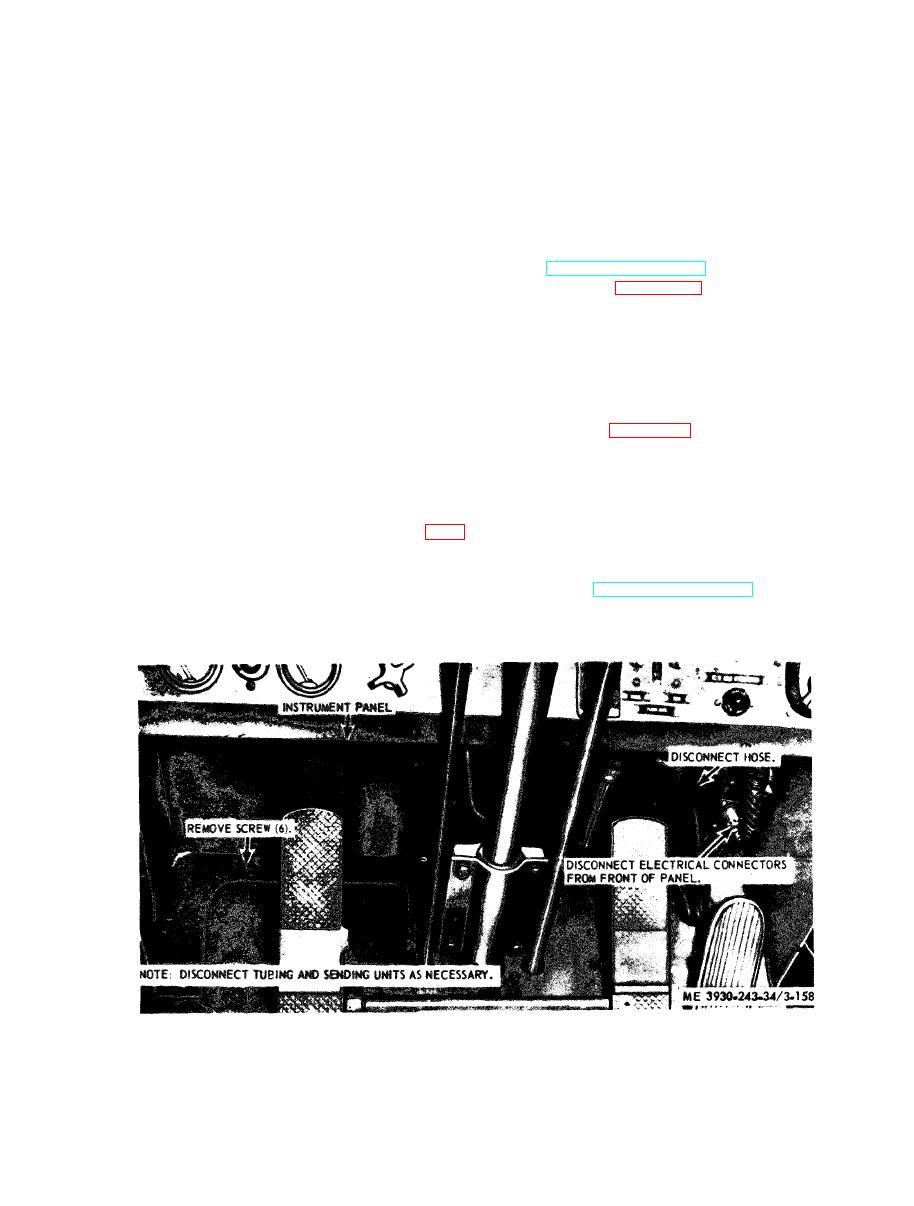
( 2 ) Refer to figure 3-158 and remove in-
of mechanical difficulty.
s t r u m e n t panel.
c. Inspection.
a. General. The boom assembly is mounted to the
(1) Inspect the instrument panel for cracks
front part of the forklift frame. There are two main
a n d damage.
parts to the boom assembly, the outer boom and the
( 2 ) Inspect a l l m o u n t i n g h a r d w a r e f o r
innerslide.
damage or missing parts.
b. Removal. Remove the boom assembly (para 2-
d. Installation.
11).
(1) Refer to figure 3-158 and install the in-
c. Inspection.
s t r u m e n t panel.
(1) Inspect the outer boom and the innerslide
(2) Install the clutch oil pressure gage, engine
for cracks and breaks.
oil pressure gage, brake oil pressure gage (Model
(2) Inspect the mounting points and hardware
RTL-10), converter temperature gage, water
for cracks and breaks.
temperature gage, brake pressure gage valves
( M o d e l RTL-10), ammeter, hourmeter, ignition
2-11).
switch, start button, bank indicator (Model RTL
1 0 - 1 ) , flood light and head light switches, and
a. General. The instrument panel is mounted to
panel lights (TM 10-3930-243-12).
the front of the driver's compartment and contains
all the instruments, gages and switches.
|
|
Privacy Statement - Press Release - Copyright Information. - Contact Us |
