 |
|||
|
|
|||
|
Page Title:
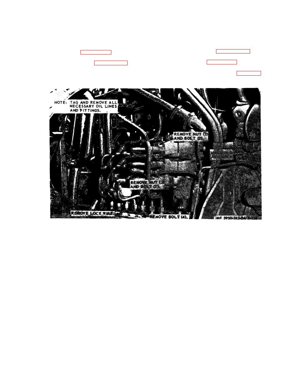
Figure 3-138. Hydraulic steering manifold, removal and installation. |
|
||
| ||||||||||
|
|
 3-68. Hydraulic Steering Manifold
(1) Inspect the tubing for cracks, kinks and
breaks.
a. General. The hydraulic steering manifold is
( 2 ) Inspect the relief valve for cracks and
mounted to the left side of the fork lift, aft of the
damage.
e n g i n e . The manifold consists of the unloader
(3) Inspect unloader valve for damage.
valve, relief valves and piping.
reassemble the hydraulic steering manifold.
the hydraulic steering manifold assembly.
the hydraulic steering manifold.
disassemble hydraulic steering manifold assembly.
d. Inspection.
|
|
Privacy Statement - Press Release - Copyright Information. - Contact Us |
