 |
|||
|
|
|||
|
Page Title:
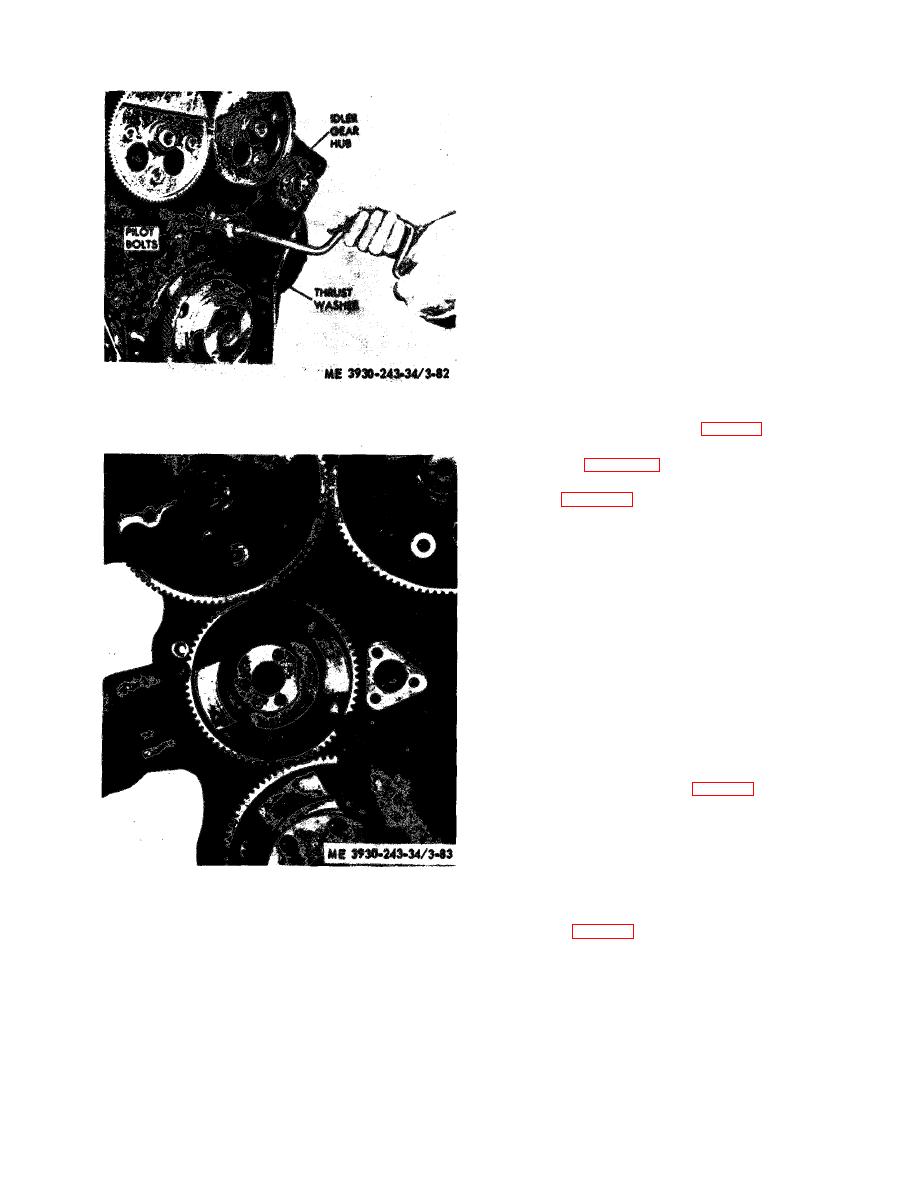
Figure 3-82. Installing idler gear hub. |
|
||
| ||||||||||
|
|
 consist of an upper shell seated in cylinder Mock
main bearing support and a lower shell seated in
main bearing cap. The bearings are numbered 1, 2,
3 , etc., indicating their respective position, and
when removed must always be reinstalled in their
original position. Lower main bearing shells have
no grooves; therefore, the upper and lower bearing
shells must not be interchanged. An oil hole in the
groove of each upper shell midway between the
parting liner registers with a vertical oil passage in
the cylinder block. Lubricating oil, under pressure
p a s s e s from the cylinder block by way of the
bearing shell to the drilled passages in the
crankshaft then to the connecting rods. Rear main
bearing thrust washers absorb the crankshaft thrust
at each side of the rear main bearing. Each washer
is made of two halves; the lower halves are doweled
to the bearing cap, the upper halves are not
doweled.
b. Removal (crankshaft in place).
(1) Remove the engine (para 2-9).
(2) Remove the oil pan to expose the main
bearing caps (para 3-24).
(3) Remove the oil pump inlet pipe and screen
assembly (para 3-25).
(4) Remove all except the rear main bearing,
dress down the head of a 1/4" x 3/4" bolt to a
thickness of 1/16". (The thickness of the dressed
down bolt head, must be less than the thickness of
the bearing shell.) Insert the bolt into the
crankshaft journal oil hole and revolve the
c r a n k s h a f t so that the bolt head contacts the
bearing shell opposite the bearing locating tang and
roll the bearing out of the block.
NOTE
Remove one main bearing cap at a time, inspect as
outlined under INSPECTION in this section, and
complete replacement of shell and reinstallation of
cap before another cap is removed.
(5) Two-piece thrust washers are used on each
side of the rear main bearing (fig. 3-84). The lower
h a l f of these washers will be removed when
r e m o v i n g the rear main bearing cap; upper half
can be removed by pushing on end of washer with a
small rod, thus forcing washer around and out on
opposite side of bearing.
(6) Remove rear main bearing upper shell by
driving on the edge of the bearing shell with a small
curved rod (fig. 3-85), at the same time revolving
a. General. The main bearing shells are of
t h e crankshaft, thus rolling the shell from its
precision type and are readily replaceable without
position.
m a c h i n i n g . They are used at each journal and
|
|
Privacy Statement - Press Release - Copyright Information. - Contact Us |
