 |
|||
|
|
|||
|
Page Title:
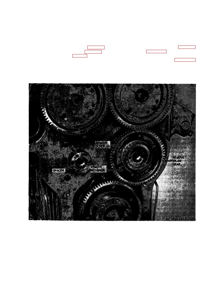
Figure 3-80. Idler gear, removal and installation. |
|
||
| ||||||||||
|
|
 washer and the gear on both shafts. The clearance
assembly, located at the flywheel end of engine,
meshes with camshaft and crankshaft gears, and
should be 0.008 to 0.015 inch, or a maximum of
rotates on a stationary hub. The hub is secured
0.019 inch with used parts.
directly to cylinder block by a bolt which passes
(8) Check the backlash between the mating
through hub, and three bolts which pass through
gears. The backlash should be 0.003 to 0.005 inch
the flywheel housing, hub and end plate.
and should not exceed 0.007 inch between used
b. Removal.
gears.
(9) Install the flywheel housing (para 3-22).
(2) Refer to figure 3-80 and remove idler gear
(10) Install the cylinder head (para 3-19).
assembly.
(11) Install the engine (para 2-9).
c. D i s a s s e m b l y . R e f e r t o f i g u r e 3 - 8 1 a n d
disassemble the idler gear assembly.
a. General. The engine idle gear and bearing
|
|
Privacy Statement - Press Release - Copyright Information. - Contact Us |
