 |
|||
|
|
|||
|
Page Title:
Section V. CAMSHAFT, CRANKSHAFT AND BEARINGS |
|
||
| ||||||||||
|
|
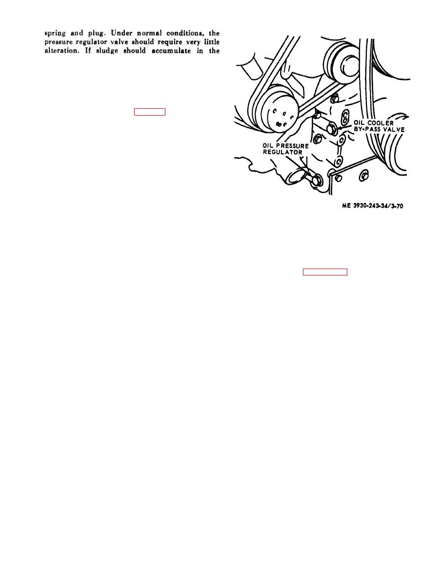 lubricating system, the valve may not work freely,
thereby remaining open or failing to open at the
normal operating pressure. The valve opening
pressure is 52 psi.
b. Removal.
(1) Remove the plug and washer from the
engine lower front cover (fig. 3-70).
(2) Withdraw the spring and the valve from
the cover.
c. Inspection. Inspect the valve spring and check
valve for freedom of movement within the engine
cover valve bore.
d. Installation.
(1) Apply clean engine oil, to the outer surface
of the valve and slide the valve into the opening in
the engine lower front cover (closed end first).
(2) Install a new copper gasket on the plug.
( 3 ) While compressing the spring, start the
plug in the cover. Tighten the plug.
Section V. CAMSHAFT, CRANKSHAFT AND BEARINGS
3-28. General
(2) Refer to figure 3-71 and remove front
cover.
The camshaft has lobes that operate the push rods
c . Disassembly. After front cover is removed,
and directly operate the valves and fuel injectors.
press oil seal from front cover.
Crankshaft thrust is taken through two piece
d. Cleaning and Inspection.
washers on each side of the rear main bearing. All
(1) Clean the front cover.
main and connecting rod bearing journal surfaces
(2) Inspect cover for cracks or damage.
a n d oil seal surfaces are induction hardened.
(3) Inspect oil seals for wear or damage,
Crankshaft wear is usually associated with bearing
replace if necessary.
troubles. Therefore, whenever main or connecting
e. Install Oil Seals.
rod bearings are inspected, the crankshaft should
(1) Support inner face of cover on woodblocks.
a l s o be inspected. The camshaft is located just
( 2 ) If outside diameter of oil seal is not
below the top of the cylinder block. The shafts are
precoated with sealant, coat the bore in cover with
supported by bearings (bushing type) that are
nonhardening sealant.
pressed into bores in the cylinder block. The
(3) Position oil seal in cover with lip of seal
c a m s h a f t is supported by end, intermediate, and
pointing toward inner face of cover.
c e n t e r bearings. Lubrication is supplied under
CAUTION
pressure to the end bearings by way of passages in
Keep lip of the oil seal clean and free of
the cylinder block which lead from the main oil
scratches.
gallery. From the end bearings, oil passes through
(4) Press oil seal into cover until seal is flush
the hollow camshaft to the intermediate and center
with bottom of counterbore.
bearings.
(5) Install second oil seal in same manner.
( 6 ) Remove excess sealant from cover and
seals.
a. General. The engine upper front cover is
f. Installation.
attached to the cylinder block with attaching bolts.
(1) Affix a new gasket to cover.
The camshaft oil seals are pressed into the cover.
(2) Install cover on engine. Tighten bolts to 35
b. Removal.
foot-pounds torque.
(1) Remove various parts and assemblies from
(3) Apply grease to the outside diameter of oil
e n g i n e upper front cover as outlined in their
seal spacers; then, slide them on the shaft.
respective paragraph of this manual.
|
|
Privacy Statement - Press Release - Copyright Information. - Contact Us |
