 |
|||
|
|
|||
|
Page Title:
Figure 3-69. Installing piston, connecting rod and liner assembly in cylinder block. |
|
||
| ||||||||||
|
|
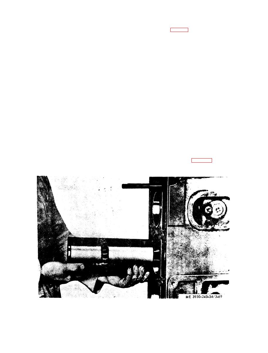 (6) Hold the piston, rod and liner in line with
f. Installation. After the piston and connecting
the block bore (fig. 3-69) so that the identification
rod assembly have been installed in the liner, the
number of the rod is facing the serial number side
entire assembly may be installed in the engine as
of the block. Also align the match marks on the
follows:
lincr and block, Slide the entire assembly into the
( 1 ) Make sure the seal ring groove in the
b l o c k bore and seal ring, being careful not to
cylinder block is clean, then install the seal ring,
damage the seal ring.
NOTE
(7) Pull or push the piston and connecting rod
The Current cylinder block has an additional seal ring
down until the upper bearing seats firmly on the
groove approximately 1/8" below the top groove. This
crankshaft journal; use care so the hearing shell
groove will permit further use of the cylinder block
will not be dislodged from the rod.
where erosion or corrosion of the upper seal ring
(8) Place the lower bearing shell (the one with
groove has occurred. The lower seal ring groove in the
current cylinder block has been eliminated. Rein-
the continuous oil groove) in the connecting rod cap
stallation of the seal ring in the former block is not
with the tang on the groove in the notch in the cap.
required.
Lubricate the bearing shell with clean engine oil.
(9) Install the bearing cap and shell on the
(2) Apply vegetable type shortening or per-
connecting rod with the number on the cap and rod
manent type antifreeze solution to the seal ring.
adjacent to each other. Tighten the connecting rod
(3) If any pistons and liners are already in
nuts (3/8-24 bolts) to 45-50 lbs. ft. (lubricated) or
place, use holddown clamps to keep the liners in
50-55 lbs. ft. plain.
place when the crankshaft is rotated.
(10) Check the connecting rod side clearance.
(4) Rotate the crankshaft until the connecting
T h e clearance should be 0.006" to 0.012" new
rod journal of the particular cylinder being worked
on is at the bottom of its travel, wipe the journal
parts.
(11) Remove holddown clamps. Install new
clean and lubricate it with clean engine oil.
compression gaskets, water and oil seals and install
(5) Install the upper bearing shell (the one
the cylinder head,
with a short groove at each parting line) in the
c o n n e c t i n g rod. L u b r i c a t e the shell with clean
(12) Install oil pan (para 3-24), and refer to
current LO and fill crankcase with engine oil.
engine oil.
The valve is located in an oil gallery within the
l o w e r front cover and is held tight against a
a. General. The regulator assembly consists of a
hollow piston type valve, a spring gasket and plug.
c o u n t e r b o r e valve seat by the compressed
|
|
Privacy Statement - Press Release - Copyright Information. - Contact Us |
