 |
|||
|
|
|||
|
Page Title:
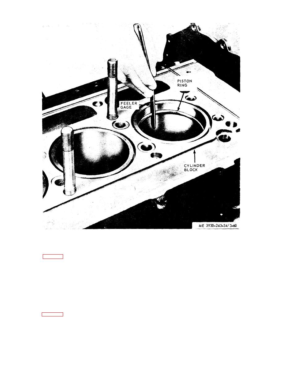
Figure 3-60. Measuring piston ring gap with feeler gage. |
|
||
| ||||||||||
|
|
 which may vary0.001 inch, and ring clearances
(k) Check the ring clearances in the piston
in grooves should be as follows:
grooves (fig. 3-61). Nominal ring groove width,
Upper compression (fire) ring (straight face)
-0.007
in.
-0.010 in.
Upper compression (fire) ring (tapered face)
-0.003
in.
-0.006 in.
Second compression ring
-0.007
in.
-0.010 in.
Third compression ring
-0.005
in.
-0.008 in.
Lower compression ring
-0.005
in.
-0.008 in.
Upper oil control ring
-0.0015
in.
-0.0055 in.
Lower oil control ring
-0.0015
in.
-0.0055 in.
(2) Wear limits. For allowable wear limits
(3) Connecting rod, piston pins, and bearings.
refer to table 1-1.
(a) Check rod for straightness. Hydrostatic
|
|
Privacy Statement - Press Release - Copyright Information. - Contact Us |
