 |
|||
|
|
|||
|
|
|||
| ||||||||||
|
|
 ensure a good seal between the cylinder head and
(1) Check the cylinder liner flange height with
block. Therefore, it is vitally important that the
relationship to the cylinder block.
cylinder head be installed with the utmost care.
(2) Check to be sure the top of the pistons are
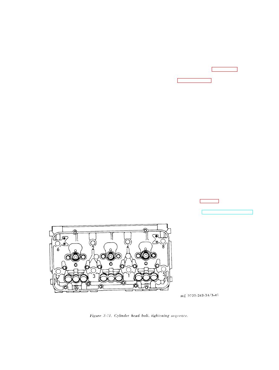
Install cylinder head bolts; then, beginning on the
clean and free of foreign material.
camshaft side of the head, take up the tension in the
(3) Check to see that each push rod is threaded
into its clevis until the end of the push rod projects
cam follower springs by tightening the bolts lightly.
through the clevis. This is important since serious
Finally tighten the bolts to 170-180 foot-pounds
engine d a m a g e w i l l b e p r e v e n t e d w h e n the
torque with a torque wrench about one-half turn at
crankshaft is rotated during tune-up.
a time, in the sequence shown in figure 3-41.
(4) To avoid damage to the water and oil seals,
(4) If the injectors were not previously in-
check to be sure that the groove and the coun-
stalled, refer to paragraph 3-14 and install injectors
terbores in the top of the cylinder block are clean
at this time.
and smooth.
(5) Set injector control tube assembly in place
on cylinder head and tighten hold-down bolts,
g. Install Cylinder Head.
finger tight only. When positioning injector control
(1) Install new cylinder head compression
gaskets and seals as outlined below:
tube be sure that ball end of injector control rack
levers engage the slots in the injector control racks.
(a) Install a new compression gasket on each
cylinder liner.
With one end of the control tube return spring
hooked around one injector rack control lever and
(b) Place new seal rings in the counterbores
of the water and oil holes in the cylinder block.
the other end hooked around the control bracket,
tighten bracket bolts with a 7/16 inch universal
(c) Install a new oil seal in the milled groove
near the outer edge of the area covered by the
socket wrench to 10-12 foot-pounds torque. After
cylinder head.
tightening bolts, revolve tube and see if the return
spring pulls the injector racks OUT (NO-FUEL
NOTE
POSITION) after they have been moved all the
Water seals, oil seals, and compression gaskets should
way IN (FULL FUEL POSITION). Since the
never be reused.
injector control tube is mounted in self-aligning
(2) To install the cylinder head without
bearings, tapping the tube lightly with a soft
disturbing the gaskets and seals, special guide studs
hammer will remove any bend that exists. The
must be used. Install the cylinder head guide studs,
injector rack must return to the no fuel position
in the end cylinder block bolt boles. Wipe the
freely by aid of the return spring only. Do not bend
bottom of the cylinder head clean; then, lower the
the return spring to bring about this condition.
head on the block.
(6) Install fuel rod (fig. 3-38).
(3) The cylinder head must be gradually and
(7)
Install
manifold,
thermostat
uniformly drawn down on the gaskets and seals to
h o u s i n g and thermostat (TM 10-3930-243-12).
|
|
Privacy Statement - Press Release - Copyright Information. - Contact Us |
