 |
|||
|
|
|||
|
Page Title:
Figure 3-37. Fuel pump, disassembly and reassembly. |
|
||
| ||||||||||
|
|
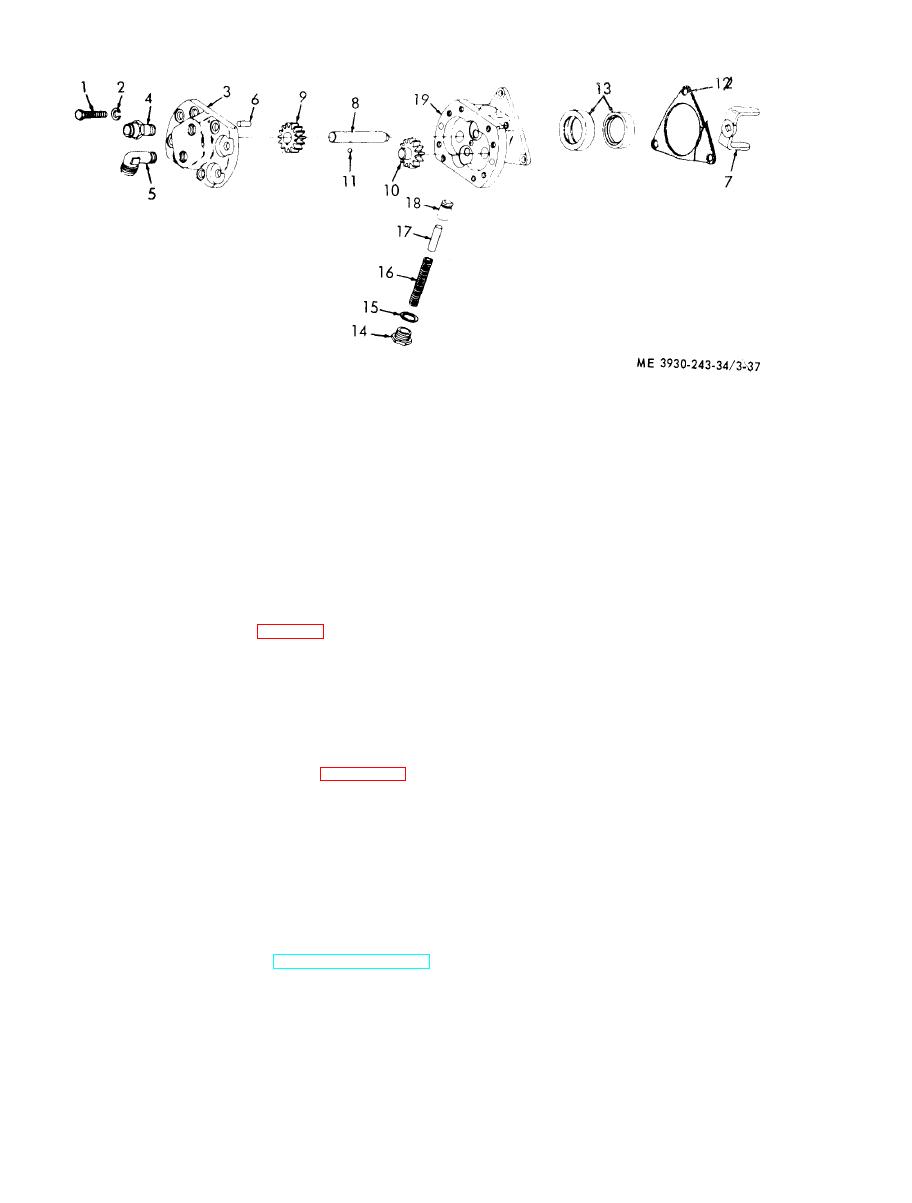 11
Gear retaining ball
1
Screw
12
Gasket
2
Lockwasher
13
Oil seals
3
Pump cover
14
Valve plug
4
Adapter
15
Gasket
5
Elbow
16
Spring
Dowel pin
6
7
17
Pin
Coupling drive fork
18
Relief valve
8 Drive shaft
19
Pump body
9 Drive gear
10 Driven gear and shaft
side of the forklift opposite the driver's seat. The
f. Inspection.
fuel tank is made from a heavy guage metal and
(1) Remove and discard the oil seals. Inspect
access steps are made on the fuel tank.
the pump drive shaft (8, fig. 3-37) for nicks and
b. Removal. R e m o v e t h e f u e l t a n k ( T M 1 0 -
scratches. Remove scratches with crocus cloth.
3930-243-12).
(2) Inspect the gear teeth (9 and 10) for
c. Testing. Install pipe plugs in all openings of
scoring or chipping.
t h e tank except one. In the remaining opening,
( 3 ) Inspect the mating faces of the housing
install a source of air pressure. Submerge the tank
(19) and cover (3) for tight fit.
in water and apply approximately 15 psi of air. If
(4) Inspect the relief valve (18) for score
marks and proper fitting into seat of pump housing.
air bubbles appear, they denote a leak. Repair, or
replace the fuel tank if damaged beyond repair.
g. Reassembly. Refer to figure 3-37 and
After repair, retest the fuel tank.
reassemble the fuel pump assembly. Reassembly
WARNING
is the reverse procedure of disassembly.
B e f o r e attempting to weld or braze the
NOTE
fuel tank, steam clean the tank for a
After assembly rotate the pump shaft by hand to
minimum of eight (8) hours. Remove
make certain that the parts rotate freely. When the
fuel cap and open the discharge and
shaft does not rotate freely, attempt to free it by
return lines during the welding process.
tapping a corner of the pump.
Failure to observe this warning may
h. Installation.
r e s u l t in serious injury or death.
(1) Remove caps from fuel lines.
d. Installation. I n s t a l l t h e f u e l t a n k ( T M 1 0 -
( 2 ) Install fuel pump (TM 10-3930-243-12).
3930-243-12).
3-17. Fuel Tank
a. General. The fuel tank is located on the right
|
|
Privacy Statement - Press Release - Copyright Information. - Contact Us |
