 |
|||
|
|
|||
|
|
|||
| ||||||||||
|
|
 d i r e c t current voltmeter to the starter terminal and
3-10. S t a r t i n g M o t o r
t h e starter housing. With voltage adjusted to 22.5
a. General. The starter is mounted to the
v o l t s , the current should be 80 amperes maximum
flywheel housing. It is 24 volt DC. The starter
at 3,600 rpm. If current and speed are both low,
components are totally enclosed to protect them
inspect for high resistance in the internal con-
from road dirt, icing conditions and road splash.
nections. If current is high and speed is low, inspect
b. Removal. Remove the starter (TM 10-3930-
the bearings and armature for binding and in-
243-12).
correct alignment.
disassemble the starting motor in numerical
n e c t e d as in (1) above, fasten a torque arm and a
sequence.
spring scale to the armature at the drive end. Adjust
d. Inspection.
the rheostat to give 3.52 volts. The correct readings
( 1 ) Inspect field coils, armature and insulating
are 500 amperes and a stall torque of 20 foot-
parts for any damage.
pounds minimum. The stall torque is the product of
(2) Inspect bushing for excessive wear.
the spring scale reading in pounds multiplied by the
(3) Inspect brushes for excessive wear.
torque arm in feet. If the current and torque are
Replace a defective or worn part.
b o t h low, inspect for high resistance in the internal
c o n n e c t i o n s and for improper brush contact. High
reassemble the starting motor. Reassembly is the
current and low torque may be caused by a
reverse procedure of disassembly.
defective armature or field coil.
f. Bench Testing.
g. Installation. Install the starting motor (TM
(1) No load test. Connect a 24 volt battery in
10-3930-243-12).
series with a load rheostat and an ammeter shunt of
h. On-Equipment Testing. Refer to TM 10-
a capacity greater than 50 amperes and connect
3930-243-12 for on-equipment testing procedures.
this group to the
housing. Connect
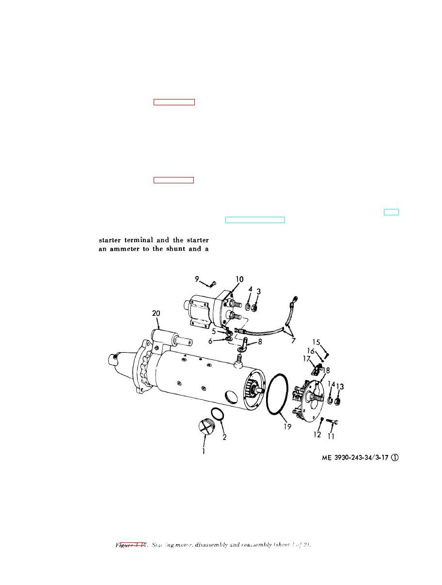
1 1 Screw
1
Plug
12 Lockwasher
2
Gasket
13
Nut
3
Nut
14
Lockwasher
4
Lockwasher
15
Screw
5
Nut
16
Lockwasher
6
Lockwasher
17
Brush
7
Lead
18
End bell
8
Connector
19
Packing
9
Screw
10
20
Starter assembly
(1) Starter and brushes
|
|
Privacy Statement - Press Release - Copyright Information. - Contact Us |
