 |
|||
|
|
|||
|
|
|||
| ||||||||||
|
|
 REPAIR OF FORKLIFT
Section I. ENGINE ACCESSORIES
3-1. General
not be less than 0.004 inch nor more than 0.011
This section contains information on the main-
inch.
tenance of those items considered to be engine
(2) Using a micrometer depth gage, measure
accessories. These items consist of the oil pump, oil
distance from face of pump body (7) to sides of
cooler, air inlet housing, blower assembly, limiting
inner ( 10) and outer ( 11 ). Clearance should not be
speed mechanical governor, water pump, engine
less than 0.001 inch nor more than 0.0035 inch.
generator and starter.
NOTE
3-2. Oil Pump and Crankshaft Pulley
Rotors are obtainable only in matched sets.
a. General. The rotor type oil pump is bolted to
e. Reassembly. Reassembly is the reverse order
inside of the lower engine front cover and driven
of disassembly. Refer to figure 3-3 and reassemble
directly by the crankshaft. Oil is directed to the
the oil pump.
lower engine front cover and then to a mail oil
f. Installation.
gallery in the cylinder block, under pressure, to the
(1) Refer to figure 3-2 and install the oil pump
main bearings, balance shaft, and crankshaft
and crankshaft pulley.
bearings. The crankshaft pulley is used to drive the
(2) Install the oil pan (fig. 3-1).
engine generator and the radiator fan.
(3) Install the engine (para 2-9).
b. Removal.
(1) Remove the engine (para 2-9).
(2) Remove the oil pan (fig. 3-1).
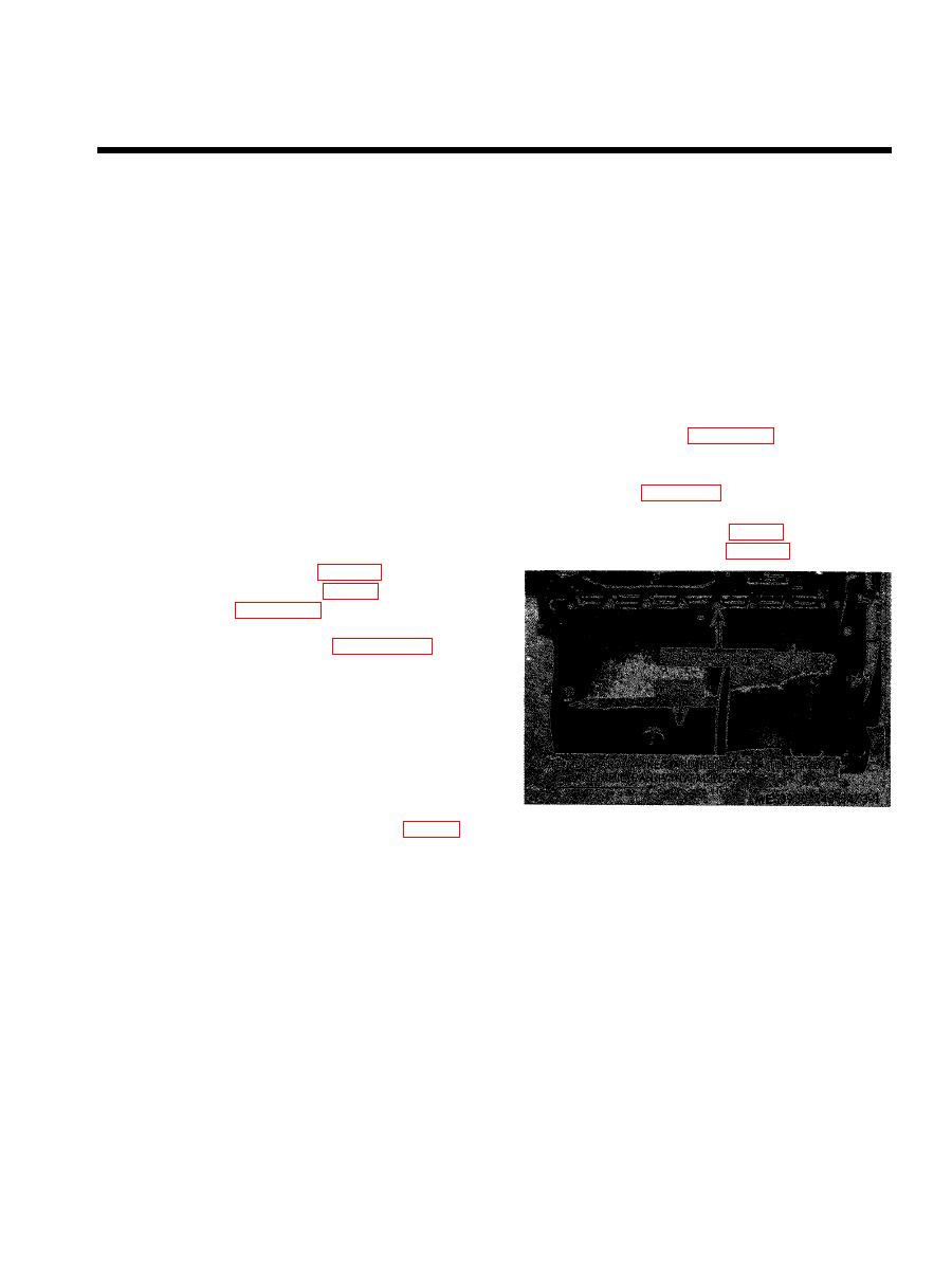
(3) Refer to figure 3-2 and remove the oil
pump and crank shaft pulley.
c. Disassembly. Refer to figure 3-3 and
disassemble the oil pump in numerical sequence.
NOTE
Clean pump thoroughly to remove all traces of dirt,
sand, or foreign matter which might damage the
pump. Discard all gaskets and replace with new one
upon reassembly.
d. Inspection.
(1) The greatest amount of wear in the oil
pump occurs on the lobes of the inner ( 10, fig. 3-3)
and outer (11 ) rotor of each lobe. Clearance should
|
|
Privacy Statement - Press Release - Copyright Information. - Contact Us |
