 |
|||
|
|
|||
|
Page Title:
Section IV. REMOVAL AND INSTALLATION OF MAJOR COMPONENTS AND AUXILIARIE |
|
||
| ||||||||||
|
|
 (3) I n s p e c t i n g g e a r s .
s c o r e s , scratches and burrs. Remove defects with a
or broken teeth. If the defect cannot be removed
soft stone. If scores and scratches cannot be
with a soft stone, replace the gear.
removed with a soft stone, replace the gear.
(b) Inspect gear teeth for wear that may
have destroyed the original tooth shape. If this
condition is found, replace the gear.
Section IV. REMOVAL AND INSTALLATION OF MAJOR COMPONENTS AND AUXILIARIE
2-8. General
p u l l e y , r a d i a t o r h o s e s , a i r i n t a k e d u c t, v o l t a g e
regulator base, hoses, and lines (TM 10-3930-
T h i s section provides instructions for removal and
243-12).
i n s t a l l a t i o n of the major components of the forklift
t r u c k . The major components in this section consist
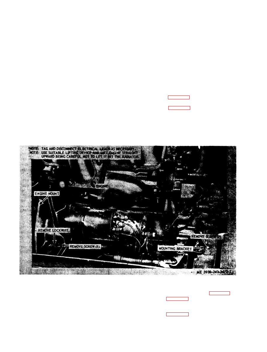
(2) Refer to figure 2-1 and remove the engine.
b. Installation.
of the engine, torque convertor, transmission and
transfer assembly, the mast column assembly, and
( 1 ) Refer to figure 2-1 and install the engine.
(2) Install the lines, cables, hoses, voltage
the axle assembly. Refer to the appropriate
r e g u l a t o r base, air intake duct, radiator hoses, fan
paragraphs in this section for each assembly.
pulley, universal joint, and top panel (TM 10-
2-9. Engine
3930-243-12).
a. Removal.
(1) Remove the top panel, universal joint, fan
(2) Remove the mast
assembly (para 2-11).
T r a n s f e r Assembly
(3) Refer to figure 2-2
and remove the torque
a. Removal.
convertor, transmission and
transfer assembly.
(1) Remove the universal joints, top panel,
b. Installation.
h y d r a u l i c valves, linkage, lines and hoses (TM 10-
( 1 ) Refer to figure 2-2
and install the torque
3930-243-12).
convertor, transmission and
transfer assembly.
|
|
Privacy Statement - Press Release - Copyright Information. - Contact Us |
