 |
|||
|
|
|||
|
Page Title:
Section VII. RADIO INTERFERENCE SUPPRESSION |
|
||
| ||||||||||
|
|
 Section
VII.
RADIO
INTERFERENCE
SUPPRESSION
r e p l a c e m e n t of secondary suppression components,
4 - 1 0 A . General Methods Used to Attain Proper
refer to the applicable maintenance sections of this
Suppression
manual.
E s s e n t i a l l y , suppression is attained by providing a
Testing
of
Radio
Interference
Sup-
l o w resistance path to ground for stray currents.
pression Components
T h e methods used includes shielding the ignition
and high-frequency wires, grounding the frame
If interference is indicated, isolate the cause of
with bonding straps, and using capacitors and
interference
by
the
trial-and-error
method
of
resistors. F o r g e n e r a l i n f o r m a t i o n o n r a d i o i n -
replacing each suppression component in turn,
terference suppression, see TM11-483.
until the cause of interference is located and
eliminated.
4-11.
Interference
Suppression
Components
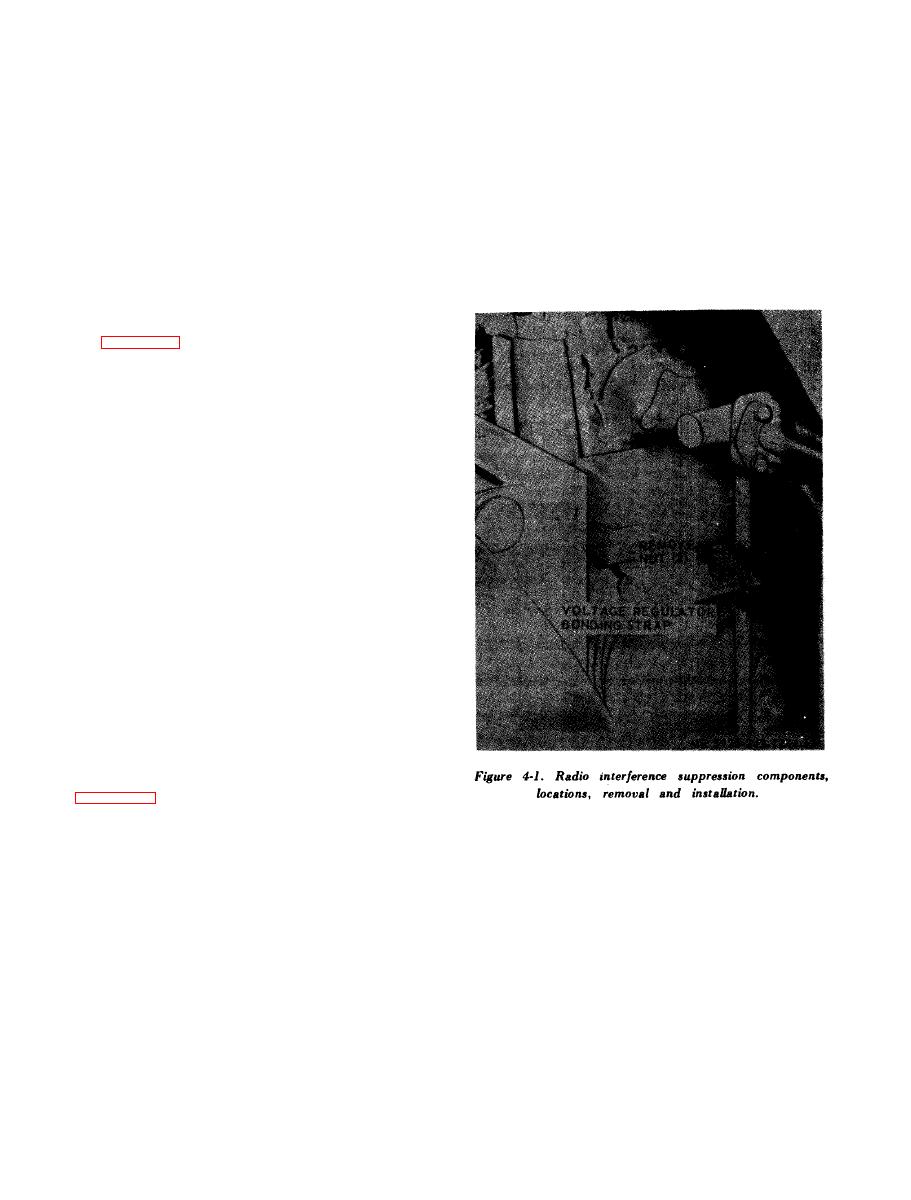
a. Primary Suppression Component. The in-
t e r f e r e n c e suppression bonding strap is illustrated
on figure 4-1.
b.
Secondary
Suppression
Components.
(1) T o o t h - t y p e l o c k w a s h e r s .
(a) T h e g e n e r a t o r i s m o u n t e d o n t h e t o p
front of the engine and is grounded by internal-
e x t e r n a l toothed lockwashers.
the main frame near the left rear end of the engine
a n d is grounded by internal-external toothed lock-
washers and bonding strap.
(2) C a p a c i t o r . T h e i n t e r f e r e n c e s u p p r e s s i o n
capacitor is located in the generator voltage
regulator.
(3) S h i e l d e d c a b l e s . T h e e n g i n e g e n e r a t o r i s
equipped with a shielded cable connecting the
g e n e r a t o r and the generator regulator.
4-12. Replacement of Suppression Components
Replace radio interference components with new
components that are identical. It is essential that a
good metal-to-metal contact is achieved to maintain
proper radio interference suppression. To correct
faulty suppression, substitute new interference
suppression c o m p o n e n t s u n t i l t h e f a u l t y c o m -
ponents are discovered.
a. Primary Suppression Component. Refer to
b.
Secondary
Suppression
Components.
For
Section
VIII.
MAINTENANCE
OF
for
(2) Inspect all electrical wiring
d e t e r i o r a t i o n of insulation, cuts and bare wires.
a. Cleaning.
(3) Inspect all hoses for cuts, deterioration,
(1) Clean all parts in an approved cleaning
l e a k s and loose fittings.
solvent, e.g., Fed P-D-680.
(4) Inspect all lines for dents, cracks and leaks.
( 2 ) Clean surfaces and install new gaskets as
(5) Inspect all hardware
for
damage,
rust,
required.
breaks and damaged threads.
( 3 ) When using air use dry low pressure air.
drive
belts
for
cuts
and
(6) Inspect
b. Inspection.
( 1 ) Inspect all parts visually before installing
or reinstalling for cracks, wear, rust, corrosion.
Engine
Assembly
c u t s , breaks and dents,
This section contains information on the main-
|
|
Privacy Statement - Press Release - Copyright Information. - Contact Us |
