 |
|||
|
|
|||
|
Page Title:
Oscillating Cylinder Check Valve |
|
||
| ||||||||||
|
|
 TM 10-3930-242-34
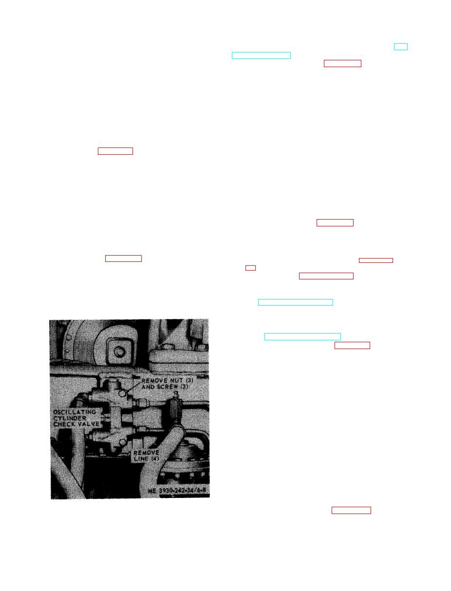
6-8. Oscillating Cylinder Check Valve
stall t h e h y d r a u l i c slave c y l i n d e r ( T M
10-3930-242-12).
a. General. The purpose of the oscillating cy-
linder check valve is to hold the machine stable
m o v e the hydraulic slave cylinder.
d u r i n g any type of operation. Should the check
v a l v e malfunction the machine will lean to the
NOTE
s i d e when operating on a slope. The oscillating
The Army model 200 and Army model 222 cylinders
c y l i n d e r check valve is located on the front of
a r e of identical construction and have identical
components. The cylinder used on the Army model
the forklift between the two automatic slack ad-
202 has slightly different internal components, but
justers.
maintenance procedures are similar. The hydraulic
b. Removal.
slave cylinder for the Army model 202 is illustrated
(1) Raise the extension boom assembly and
in TM 10-3930-242-34P/2.
i n s t a l l safety supports.
c. Cleaning and Inspection.
(2) Refer to figure 6-8 and remove the oscil-
(1) Clean all metal parts thoroughly, using
l a t i n g cylinder check valve.
solvent
P-D-680, or
equal.
Dry parts
thoroughly.
c. Cleaning and Inspection.
(1) Clean the oscillating cylinder check
(2) Inspect the parts for wear, scored areas,
s c r a t c h e s , nicks, and burrs.
valve thoroughly, using solvent P-D-680, or
( 3 ) Inspect the cylinder for cracks and dis-
equal.
tortion.
(2) Inspect the valve for leakage, cracks and
( 4 ) Replace defective parts.
damage.
(3) Replace a damaged or leaking check
s e m b l e the hydraulic slave cylinder.
valve. A slight leak will cause the valve to mal-
function.
NOTE
d . Installation.
Upon reassembly, use new packing. Torque the
(1) Refer to figure 6-8 and install the oscil-
rod end nut to the value specified in paragraph
l a t i n g cylinder check valve.
1-7b (8),
( 2 ) Remove safety supports and lower the
e x t e n s i o n boom assembly.
h y d r a u l i c slave cylinder in a similar manner.
f. Installation. Install the hydraulic slave cy-
6-9. Hydraulic Slave Cylinder
linder (TM 10-3930-242-12).
a. Removal and Installation. Remove and in-
6-10. Hydraulic Side Shift Cylinder
a. Removal. Remove the hydraulic side shift
cylinder (TM 10-3930-242-12).
a s s e m b l e the hydraulic side shift cylinder.
NOTE
The Army model 200 and Army model 222 cylin-
ders are of identical construction and have identi-
cal components. The cylinder used on the Army
model 202 has slightly different internal compo-
n e n t s , but maintenance procedures are s i m i l a r .
T h e hydraulic side shift cylinder for the Army
model 202 is illustrated in TM 10-3930-242-34P/2.
c. Cleaning and Inspection.
(1) Clean all metal parts thoroughly, using
solvent P-D-680, or equal. Dry all parts
thoroughly.
(2) Inspect the parts for wear, scored areas,
s c r a t c h e s , nicks and burrs.
(3) Inspect the cylinder for cracks and dis-
tortion.
( 4 ) Replace defective parts.
Figure 6-8. oscillating cylinder check valve, removal and
s e m b l e the hydraulic side shift cylinder.
installation.
|
|
Privacy Statement - Press Release - Copyright Information. - Contact Us |
