 |
|||
|
|
|||
|
|
|||
| ||||||||||
|
|
 TM 10-3930-242-34
assembly, reassembly and installation.
m a y vary from vehicle to vehicle, the dimen-
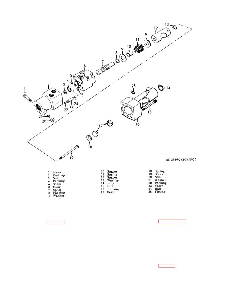
e. Installation. Reinstall the hydraulic power
s i o n a l settings listed in paragraph 1-7b should
steering valve (fig. 5-20). Remove caps from
b e regarded as being of nominal values and a
hydraulic line and reinstall the lines to the
s t a r t i n g point for the following procedure:
valve.
a. Lift vehicle so that rear wheels are off
NOTE
g r o u n d . Although not mandatory, it is recom-
No pressure setting at the valve is required. Check
m e n d e d that the front wheels be raised off the
pressure at the pump. Correct pressure is 2,000 25
g r o u n d also.
psi.
b. T u r n s t e e r i n g w h e e l t o p o s i t i o n w h e r e
scribe mark on steering sector shaft is 6 clock-
This adjustment procedure will provide
w i s e from the horizontal. This establishes the
p r o p e r functioning of the steering system. Be-
straight ahead position (fig. 5-19).
c a u s e part dimensions and installation locations
|
|
Privacy Statement - Press Release - Copyright Information. - Contact Us |
