 |
|||
|
|
|||
|
|
|||
| ||||||||||
|
|
 TM 10-3930-242-34
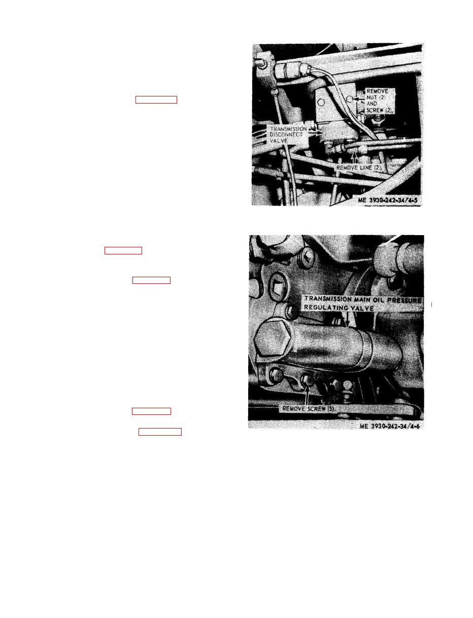
NOTE
The main oil pressure regulating valve may be ad-
justed by adding or removing shims. Each shim will
raise or lower pressure approximately 10 psi.
t a l l transmission main oil pressure regulating
valve.
4-5. Transmission Control Valve
a. General. The transmission control valve is
s e c u r e d to the side of transmission housing by
11 bolts and lockwashers. The control valve
b o d y assembly houses the forward-reverse con-
t r o l valve assembly, the range selector valve
and the clutch cut off valve.
b. Removal.
stallation.
(1) Remove access panel from under right
rear fender.
(2) Refer to figure 4-8 and remove the con-
trol valve.
s e m b l e control valve in numerical sequence.
d. Cleaning and Inspection.
(1) Clean all parts thoroughly, using sol-
v e n t P-D-680, or equal.
(2) Clean all oil passages.
( 3 ) Inspect cast for nicks, scratches, and
g r o o v e s . Remove burrs with crocus cloth. Re-
place parts that are deeply grooved or
scratched.
( 4 ) Inspect threaded openings for damaged
threads.
s e m b l e control valve.
t h e control valve.
ing valve, removal and installation.
|
|
Privacy Statement - Press Release - Copyright Information. - Contact Us |