 |
|||
|
|
|||
|
Page Title:
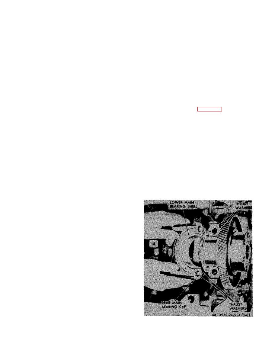
Figure 3-61. Rear main bearing thrust washer and mounting |
|
||
| ||||||||||
|
|
 TM 10-3930-242-34
lower shell should be installed. If a new
(3) The thickness of the bearing shells
should be measured at point C, 90 from parting
crankshaft is used all new bearing shells
line.
should be installed.
NOTE
(1) When installing the upper main bearing
Minimum thickness of a worn standard main bear-
s h e l l s with crankshaft in place, start the end of
ing shell is 0.123 inch and, if any of the shells are
t h e shell having no tang around the crankshaft
t h i n n e r than this dimension, all shells must be
j o u r n a l , so that when shell is in place the tang
d i s c a r d e d and replaced with new shells. A new
will fit into the groove in the shell support.
bearing shell has a thickness of 0.1245-0.1250 inch.
(2) Assemble crankshaft thrust washer be.
(4) In addition to this thickness measure-
fore installing rear main bearing cap, Clean
m e n t , the clearance between main bearings and
b o t h halves of thrust washer carefully, remov-
crankshaft journals should be checked. This
i n g any burs from the seats-the slightest parti-
c l e a r a n c e may be determined with the crank-
cle of dirt may decrease clearance between
shaft in place by means of a soft plastic measur-
washers and crankshaft beyond limits. Slide
i n g strip which is squeezed between the journal
u p p e r halves of thrust washers into place in
a n d bearing, or with the crankshaft removed by
their grooves, as shown in figure 3-61, then as-
m e a s u r i n g the outside diameter of the crank-
s e m b l e lower halves over dowel pins in bearing
shaft main bearing journals and the inside
cap.
diameter of the main bearing shells when instal-
NOTE
l e d in place with the proper troque of 120-130
Main bearing caps are bored in position and
foot-pounds on the main bearing cap bolts. If the
marked 1, 2, 3, 4, and 5. They must be replaced in
c l e a r a n c e between any crankshaft main bearing
their original positions with marked side of caps
journal and its bearing shells exceeds 0.006
facing the same side of cylinder block that carries
the engine serial number.
i n c h , all bearings shells must be discarded and
r e p l a c e d with new shells. The proper clearance
(3) With the lower main bearing shells in-
is 0.0013-0.0042 inch.
stalled in bearing caps, install caps in their orig-
i n a l position and draw bolts up snug. Then tap
CAUTION
c a p s lightly with a soft hammer to seat them
One main bearing shell, alone, should not
p r o p e r l y , and draw bearing cap bolts uniformly
b e replaced. If one bearing shell re-
t i g h t , starting with center cap and working al-
q u i r e s replacement, a new upper and
ternately towards both ends of block, to 120-130
lower shell should be installed.
f o o t - p o u n d s torque.
(5) When main bearing replacement is
n e c e s s a r y , it is very important that the crank-
shaft journals be thoroughly inspected before
n e w replacement bearings are installed. Very
o f t e n , after prolonged engine operation, a ridge
i s formed on the circumference of the crank-
shaft journals in line with the journal oil holes.
This ridge must not exceed 0.0002 inch and, if it
i s not removed before new bearings are instal-
led, then during engine operation, localized high
u n i t pressures in the center area of the bearing
s h e l l will cause pitting of the bearing surface.
Also, damaged bearings may cause bending
f a t i g u e and resultant cracks in the crankshaft.
d. Installation (Crankshaft in Place).
NOTE
Make sure all parts are clean. Apply clean engine
oil to all crankshaft journals and install main
bearing shells by reversing the sequence of opera-
tions given for removal,
CAUTION
M a i n bearing shells should not be re-
p l a c e d separately. If bearing shell re-
q u i r e s replacement, a new upper and
mounting.
|
|
Privacy Statement - Press Release - Copyright Information. - Contact Us |
