 |
|||
|
|
|||
|
Page Title:
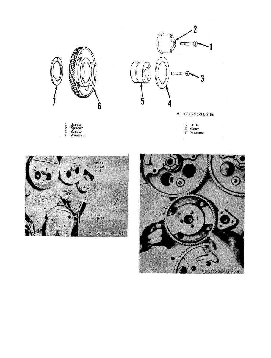
Figure 3-57. Installing idler gear hub. |
|
||
| ||||||||||
|
|
 TM 10-3930-242-34
and consist of an upper shell seated in cylinder
block main bearing support and a lower shell
s e a t e d in main bearing cap. The bearings are
numbered 1, 2, 3, etc., indicating their respective
position, and when removed must always be
der Mock. Lubricating oil, under pressure pas-
reinstalled in their original position, Lower
ses from the cylinder block by way of the bear-
m a i n bearing shells have no grooves; therefore
i n g shell to the drilled passages in the crank-
t h e upper and lower bearing shells must not bt
s h a f t then to the connecting rods. Rear main
interchanged. An oil hole in the groove of each
bearing thrust washers absorb the crankshaft
u p p e r shell midway between the parting liner
t h r u s t at each side of the rear main bearing.
registers with a vertical oil passage in the cylin-
E a c h washer is made of two halves; the lower
|
|
Privacy Statement - Press Release - Copyright Information. - Contact Us |
