 |
|||
|
|
|||
|
Page Title:
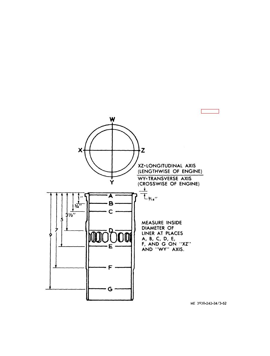
Fitting cylinder liner to bore in block: |
|
||
| ||||||||||
|
|
 TM 10-3930-242-34
3. Clamp the liner in place with a hold-
ceeds 0.003 inch, replace the liner. To check the
d o w n clamp and measure distance from top of
d i m e n s i o n s , use a dial bore gage which has a
the liner flange to top of the block. The top of the
d i a l indicator calibrated in 0,0001 inch incre-
ments.
l i n e r flange should be 0.0465-0.050 inch below
t o p of the block; and there must not be over
CAUTION
0.0015 inch difference between any two adjacent
Do not drop or slam liner against the bot-
l i n e r s when measured along the cylinder lon-
tom of counterbore in the block.
gitudinal centerline. If above limits are not met,
(d) Fitting cylinder liner to bore in block:
install liner in another bore, and recheck, or use
1. Clean inside and outside of cylinder
a new liner.
liner. Also, clean block bore and counterbore to
4. Match mark the liner and block with
i n s u r e proper seating. Then, slide the liner into
c h a l k or paint on the seral number side of en-
b l o c k until flange on liner rests on bottom of
g i n e to insure the liner is reinstalled in same
c o u n t e r b o r e in the block.
position in the same bore.
2. T a p t h e l i n e r l i g h t l y w i t h a s o f t
5. Remove holddown clamp and liner.
h a m m e r to make certain the liner flange seats
e. Reassembly.
o n bottom of counterbore.
(1) With the piston (13, fig. 3-51) assembled
|
|
Privacy Statement - Press Release - Copyright Information. - Contact Us |
