 |
|||
|
|
|||
|
Page Title:
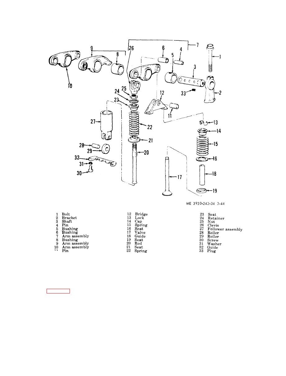
Figure 3-44. Valves and injector operating mechanism, |
|
||
| ||||||||||
|
|
 TM 10-3930-242-34
d . Remove Exhaust Valve. With the cylinder
dition, use a block of wood under cylinder head
head removed from the engine, and the valve
t o support exhaust valve.
(f) Remove cam followers and push rod
springs removed as outlined above, turn the cy-
a s s e m b l i e s (para 3-15).
l i n d e r head over and withdraw the exhaust val-
c. Inspect Exhaust Valve Spring. A f t e r r e -
ves.
moving valve spring, clean with fuel oil and dry
f r o m valve stem, wash with clean fuel oil, and
w i t h compressed air. Check spring for pitted or
f r a c t u r e d coils. Replace defective springs. The
c h e c k for scratches or scuff marks. The diame-
exhaust valve spring has an approximate free
ter of a new valve stem is 0.2480-to-0.2488-inch.
length of 2.08 inches when new, and requires a
Valve faces should be smooth, unpitted and free
load of 29 2 pounds to compress it to 1.93-inch
o f ridges or cracks. Carbon on the face of the
length.
v a l v e indicates a faulty seat and a resultant
|
|
Privacy Statement - Press Release - Copyright Information. - Contact Us |
