 |
|||
|
|
|||
|
Page Title:
Section III. CYLINDER HEAD, VALVES, FLYWHEEL, AND FLYWHEEL HOUSING |
|
||
| ||||||||||
|
|
 TM 10-3930-242-34
Section III. CYLINDER HEAD, VALVES, FLYWHEEL,
AND FLYWHEEL HOUSING
3 - 1 8 . General
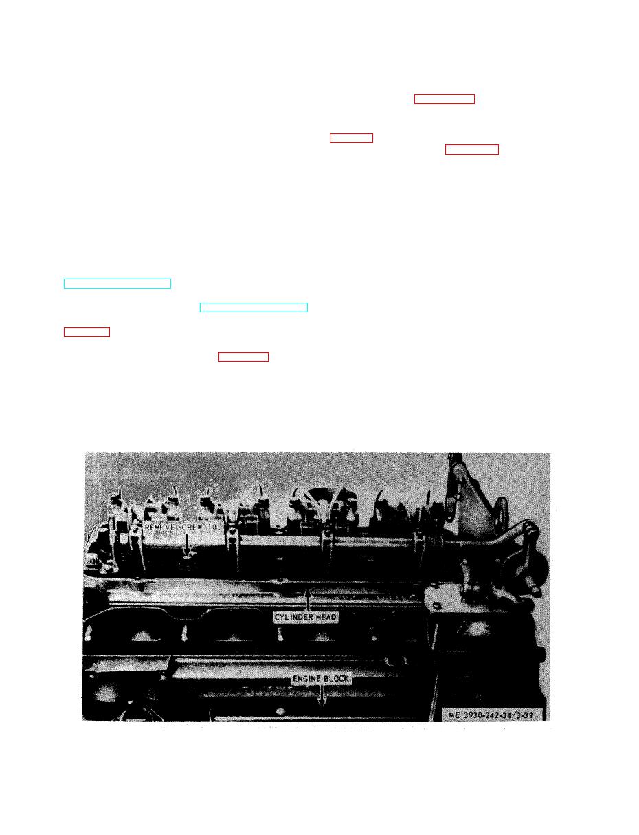
(5) Refer to figure 3-39 and remove cylinder
h e a d assembly.
This section contains maintenance informa-
( 6 ) Remove exhaust valve and valve spring
t i o n on those items that are considered compo-
(para 3-20).-
nents of the engine. These items consist of vari-
o u s parts which make up the basic engine.
a s s e m b l e cylinder head.
3-19. Cylinder Head and Valves
d. Cleaning and Inspection.
a. General. The cylinder head is a one piece
(1) Clean cylinder head. After the cylinder
c a s t i n g mounted to cylinder block. The cylinder
head has been stripped of all parts, it should be
head serves as the removable access point to the
thoroughly steam cleaned. Thoroughly clean a
u p p e r engine components and as a mounting
s e r v i c e cylinder head to remove all of the rust
m e m b e r for the valves, fuel injectors, and the
p r o o f i n g compound, particularly from the in-
exhaust manifold.
t e g r a l fuel manifolds, before the plugs are. in-
b. Removal.
s t a l l e d in the fuel manifolds and the head is
(1) Drain cooling system and engine block
m o u n t e d on an engine. A simple method of re-
(TM 10-3930-242-12).
moving the rust proofing compound is to im-
(2) Remove thermostat, thermostat hous-
m e r s e the head in solvent, oleum or fuel oil;
ing, and exhaust manifold (TM 10-3930-242-12).
then go over the head and through all openings
(3) Remove rocker arms and push rods
w i t h a soft bristled brush. After cleaning the
h e a d , it should be blown dry with compressed
t w e e n governor and injector control tube lever.
air to remove all of the solvent.
(4) Remove fuel injectors (para 3-14).
(2) Inspect cylinder head. Over a prolonged
p e r i o d of operation, the cylinder head may as-
CAUTION
sume a contour to match that the cylinder block,
When resting cylinder head assembly on
w h i c h is normal. However, if the cylinder head
work bench, protect cam follower rollers
is allowed to become overheated because of
and injector spray tips by resting valve
c o o l a n t loss, the resultant high temperatures
side of head on wooden blocks at least 2
cause stresses to occur in the casting which will
inches thick.
|
|
Privacy Statement - Press Release - Copyright Information. - Contact Us |
