 |
|||
|
|
|||
|
Page Title:
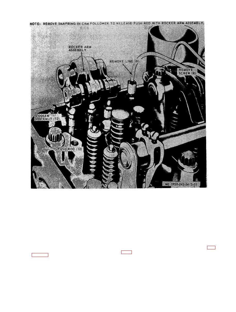
Figure 3-31. Rocker arms and push rods, removal and installation |
|
||
| ||||||||||
|
|
 TM 10-3930-242-34
stallation.
b r e a k s , and other damage. Replace damaged or
cam follower to be assured that the cam roller
d e f e c t i v e push rods.
w i l l receive proper lubrication.
( 6 ) Inspect the springs and rocker arm sup-
(9) Check the cam follower roller for smooth
p o r t for cracks, breaks, and other damage. Re-
p l a c e damaged or defective parts.
and free turning on its pin. Check for flat spots
o r scuffed marks.
(7) Inspect cam follower holes, in the cylin-
d e r head, to make sure they are clean, smooth
( 1 0 ) Measure the total clearance between
a n d free of score marks to permit proper func-
the roller bushing and pin, crosswise of pin (fig.
t i o n i n g , Inspect cam follower and cam follower
guide (fig. 3-33).
t h a n 0.010 inch diametric clearance exists, re-
p l a c e follower assembly or install a cam roller
(8) Check cam follower-to-cylinder head
and pin. Check total side clearance between rol-
clearance. This clearance should not exceed
l e r and follower; this clearance should not be
0 . 0 0 6 inch with used parts. If replacement of
less than 0.015 inch nor more than 0.023 inch.
c a m followers is necessary, use the correct type
|
|
Privacy Statement - Press Release - Copyright Information. - Contact Us |
