 |
|||
|
|
|||
|
Page Title:
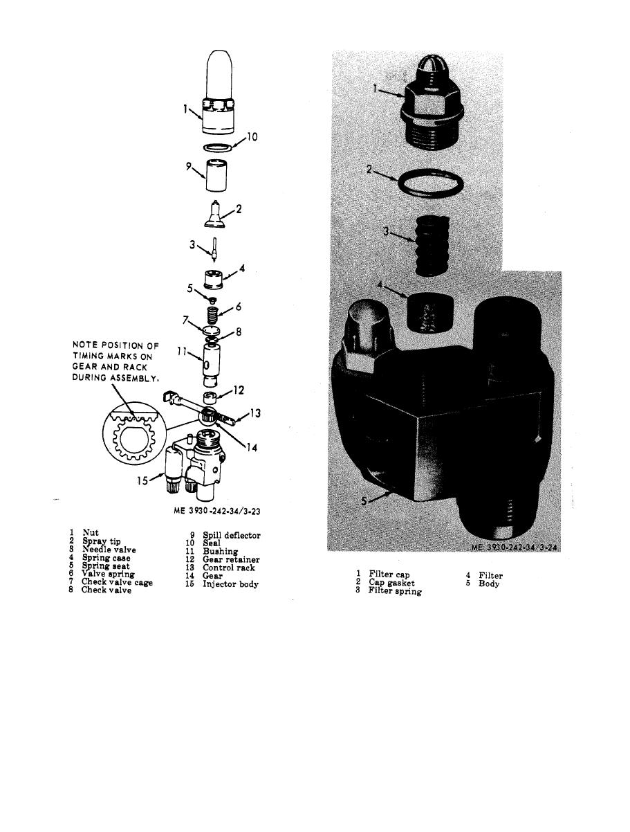
Fuel injector filter, removal and installation. |
|
||
| ||||||||||
|
|
 TM 10-3930-242-34
sembly components, removal and installation.
spring seat, spring cage, needle valve, and tip
the injector from operating properly, Check for
assembly on top of the body, Carefully place the
burs, nicks, erosion, cracks, chipping, and exces-
i n j e c t o r nut over the spray tip and valve parts,
s i v e wear. Inspect the spray tip for enlarged
and thread it on to the body. Tighten the injec-
orifices,
tor nut to 75-85 ft.-lb. torque. Remove the body
f. Needle Valve Test. With the injector nut and
w i t h the injector parts from bench vise and in-
spray tip cleaned, clamp the nonthreaded end of
s t a l l in the injector tester. Operate the pump
the body J21012-1 in a bench vise. Then, assem-
u n t i l the spray tip valve has opened several
b l e the check valve, check valve cage, spring,
times to purge air from the system. Operate the
|
|
Privacy Statement - Press Release - Copyright Information. - Contact Us |
