 |
|||
|
|
|||
|
Page Title:
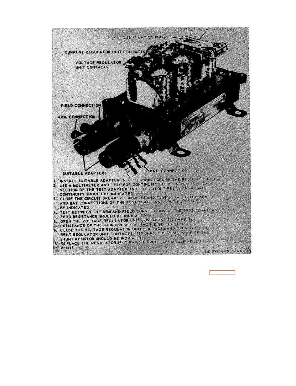
Figure 3-15. Voltage regulator adjustment (sheet 1 of 5). |
|
||
| ||||||||||
|
|
 TM 10-3930-242-34
(2) Test the field coils for an open circuit
s e m b l e the starter.
and grounds with a multimeter and with the
h. Bench Testing.
f i e l d coil assembly installed in the starter hous-
(1) No load test. Connect a 24-volt battery in
ing as instructed in TM 5-764. Test between the
series with a load rheostat and an ammeter
t e r m i n a l stud and each of the four leads of the
shunt of a capacity greater than 50 amperes and
field coil. If the multimeter fails to indicate con-
c o n n e c t this group to the starter terminal and
tinuity on anyone of the above tests, replace the
t h e starter housing. Connect an ammeter to the
field coil.
shunt and a direct current voltmeter to the
( 3 ) Test between the terminal stud and the
s t a r t e r terminal and starter housing. With the
s t a r t e r frame. If the multimeter indicates con-
voltage adjusted to 22.5 volts, the current
t i n u i t y the terminal stud is grounded and the
should be 80 amperes maximum at 3,600 rpm. If
insulating washer on the insulating bushing
t h e current and speed are both low, inspect for
m u s t be replaced.
|
|
Privacy Statement - Press Release - Copyright Information. - Contact Us |
