 |
|||
|
|
|||
|
|
|||
| ||||||||||
|
|
 TM 10-393-242-34
REPAIR OF ENGINE
Section I. ENGINE ACCESSORIES
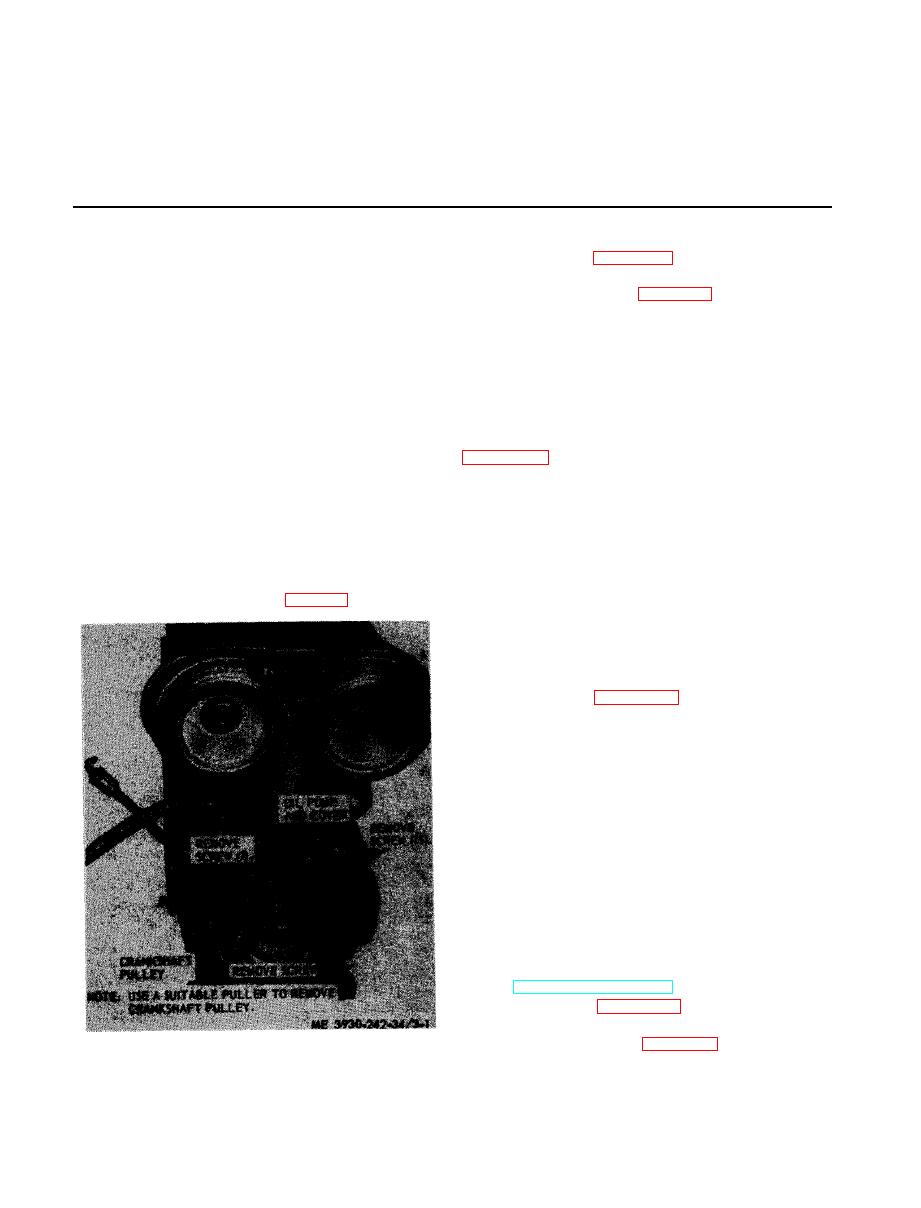
(2) Refer to figure 3-1 and remove oil pump
3 - 1 . General
and crankshaft pulley.
This section contains information on the
maintenance of those items considered to be en-
s e m b l e oil pump in numerical sequence.
g i n e accessories. They consist of the oil pump,
d. Cleaning and Inspection.
o i l cooler, air inlet housing, blower assembly,
(1) Clean the pump thoroughly with dry
speed limiting governor, radiator, generator,
c l e a n i n g solvent such as P-D-680, or equal, to
and starter.
remove all traces of dirt, sand, or foreign matter
t h a t might damage the pump.
( 2 ) The greatest amount of wear in the oil
a. General. The rotor-type oil pump is bolted
pump occurs on the lobes of the inner rotor (10,
t o back of engine lower front cover and driven
d i r e c t l y by the crankshaft. Oil is directed to
Clearance should not be less than 0.004 inch nor
lower engine front cover and then to a main oil
more than 0.011 inch.
gallery in cylinder block under pressure to main
( 3 ) Using a micrometer depth gage, meas-
b e a r i n g s , balance shaft, and camshaft bearings.
ure the distance from the face of the pump cover
The crankshaft pulley is used to drive the
(12) to sides of inner rotor (10) and outer rotor
generator and fan.
(11). Clearance should not be less than 0.001 inch
b . Removal.
nor more than 0.0035 inch,
(4) Discard the gasket (7) and seal (14).
(1) Remove the engine (para 2-5).
( 5 ) Replace all defective parts.
e. Reassembly.
NOTE
Rotors are obtainable only in matched sets.
( 1 ) Refer to figure 3-2 and reassemble the
oil pump with the exception of the seal (14).
( 2 ) Install the seal with the cup side facing
inward.
3-3. Oil Cooler
a. General. The oil cooler is attached to an oil
c o o l e r adapter attached to the cylinder block.
The flow of oil is from oil pump through a pas-
sage in the oil cooler adapter to full flow oil filter
a n d then through the oil cooler core and cylin-
der block oil galleries,
b. Removal.
(1) Drain cooling system by opening drain
cock at bottom of cooler housing.
( 2 ) Remove fuel filter, oil filter, and water
pump (TM 10-3930-242-12).
( 3 ) Refer to figure 3-3 and remove the oil
cooler.
semble oil cooler.
installation.
|
|
Privacy Statement - Press Release - Copyright Information. - Contact Us |
