 |
|||
|
|
|||
|
Page Title:
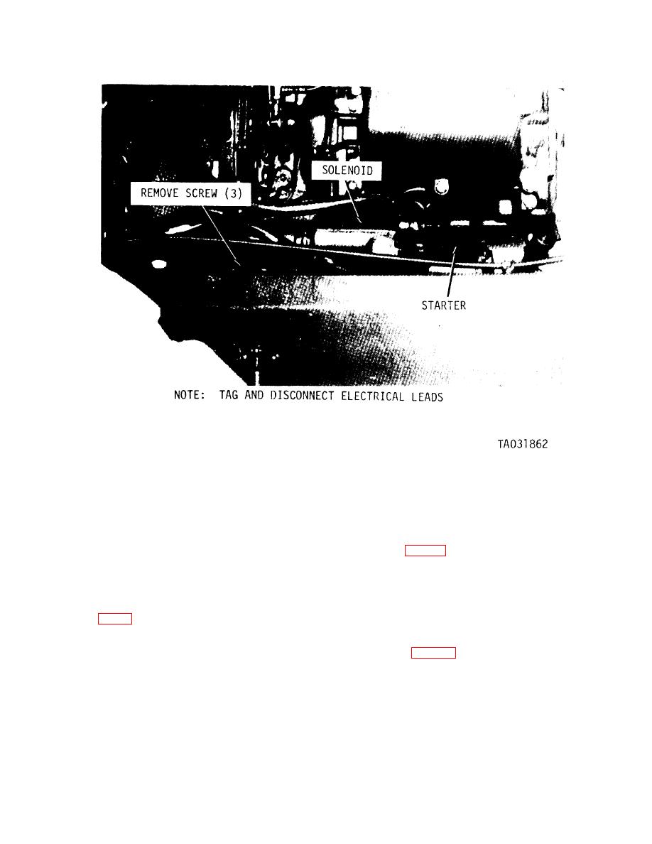
Figure 4-25. Starter and solenoid, removal and installation. |
|
||
| ||||||||||
|
|
 TM10-3930-242-12
4-38. Neutral
Start Switch
c. Installation. Refer to figure 426C and install
the neutral start switch.
a. Removal. For access to the neutral start
d. Adjustments.
switch, raise the forks to the fully raised position.
(1) Place FWD-NEUT-REV directional
The switch is located on the right front side of the
control lever (fig. 2-1) in the NEUT position.
transmission. Refer to figure 4-26 and remove the
(2) Loosen stop nut on linkage yoke (fig.
neutral start switch.
4-26B).
b. Cleaning and Inspection.
(3) Turn yoke until camshaft moves the cam,
(1) Clean the neutral start switch and direc-
strikes the roller, and the switch is activated,
tional control linkage with dry-cleaning solvent
allowing starter to engage.
(item 1, App F) and dry thoroughly.
(4) Make sure top and bottom directional
(2) Inspect the switch for corrosion. Check
linkage yokes are parallel when the directional
wiring for breaks and deterioration. Inspect linkage
control lever (fig. 2-1) is in NEUT and the high
for loose hardware and damage. Replace defective
point of the cam is striking the rollers.
parts.
|
|
Privacy Statement - Press Release - Copyright Information. - Contact Us |
