 |
|||
|
|
|||
|
Page Title:
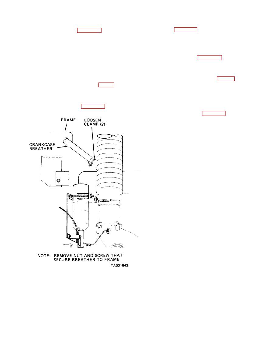
Figure 4-3. Crankcase breather, removal and installation. |
|
||
| ||||||||||
|
|
 TM10-3930-242-12
a. Refer to figure 4-4 for removal and installation,
a. Removal. Refer to figure 4-3 and remove the
of the oil level dispstick.
crankcase breather.
b. Check, clean, and repair as required.
b. Cleaning and Inspection.
WARNING
Compressed air used for cleaning pur-
poses will not exceed 30 psi. Use only
a. Removal. Refer to figure 4-4 and remove the
with effective chip guarding and personal
filler cap.
protective equipment (goggles/shield,
b. Cleaning and Inspection.
(1) Clean the oil filler pipe and cap with
gloves, etc.)
drycleaning solvent (item 1, App F) and d r y
(1) Wash the inside of the crankcase breather
thoroughly.
with drycleaning solvent (item 1, App F). Dry with
compressed air.
(2) Inspect the cap seal for deterioration.
Replace a defective or damaged seal. Inspect the
(2) Inspect the crankcase breather for cracks
and bends.
filler pipe and cap for cracks and damage. Replace a
c. lnstallation. Refer to figure 4-3 and install the
defective pipe or cap.
crankcase breather.
c. Installation. Refer to figure 4-4 and install the
oil filler cap.
|
|
Privacy Statement - Press Release - Copyright Information. - Contact Us |
