 |
|||
|
|
|||
|
Page Title:
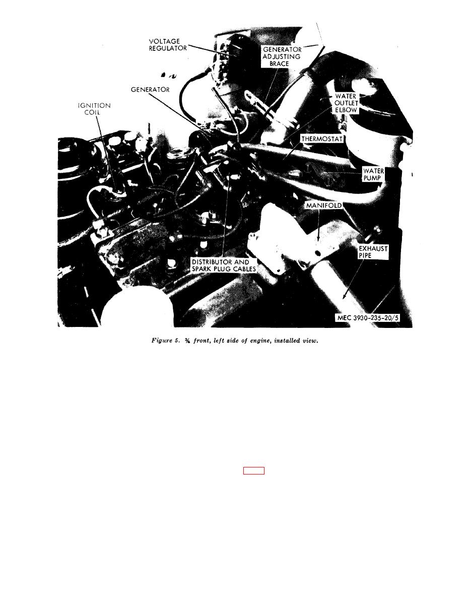
Figure 5. 3/4 front, left side of engine, installed view |
|
||
| ||||||||||
|
|
 (5) T W O adjacent low-reading cylinders
compression pressures at cranking speed is
l10 to 120 pounds (psi).
indicate a defective cylinder head gas-
ket.
h. Retest low-reading cylinders using the
oil test as follows:
(1) Add oil through the spark plug suf-
To perform a reliable vacuum test, start
ficiently to seal the piston rings.
e n g i n e and let it idle until it reaches normal
(2) Crank engine five or six times to allow
o p e r a t i n g temperature. Proceed with test as
o i l to work down around the rings,
follows:
t h e n take another compression read-
ing.
a. Stop engine when normal temperature has
been reached, then remove intake manifold plug
(3) An increase in compression indicates
defective or worn piston or rings.
(4) No increase in compression indicates
b. Start engine and observe the vacuum gage.
defective valves.
Analyze the gage readings as follows:
AGO 6217A
|
|
Privacy Statement - Press Release - Copyright Information. - Contact Us |
