 |
|||
|
|
|||
|
Page Title:
Figure 101. Hoist cylinder, exploded view. |
|
||
| ||||||||||
|
|
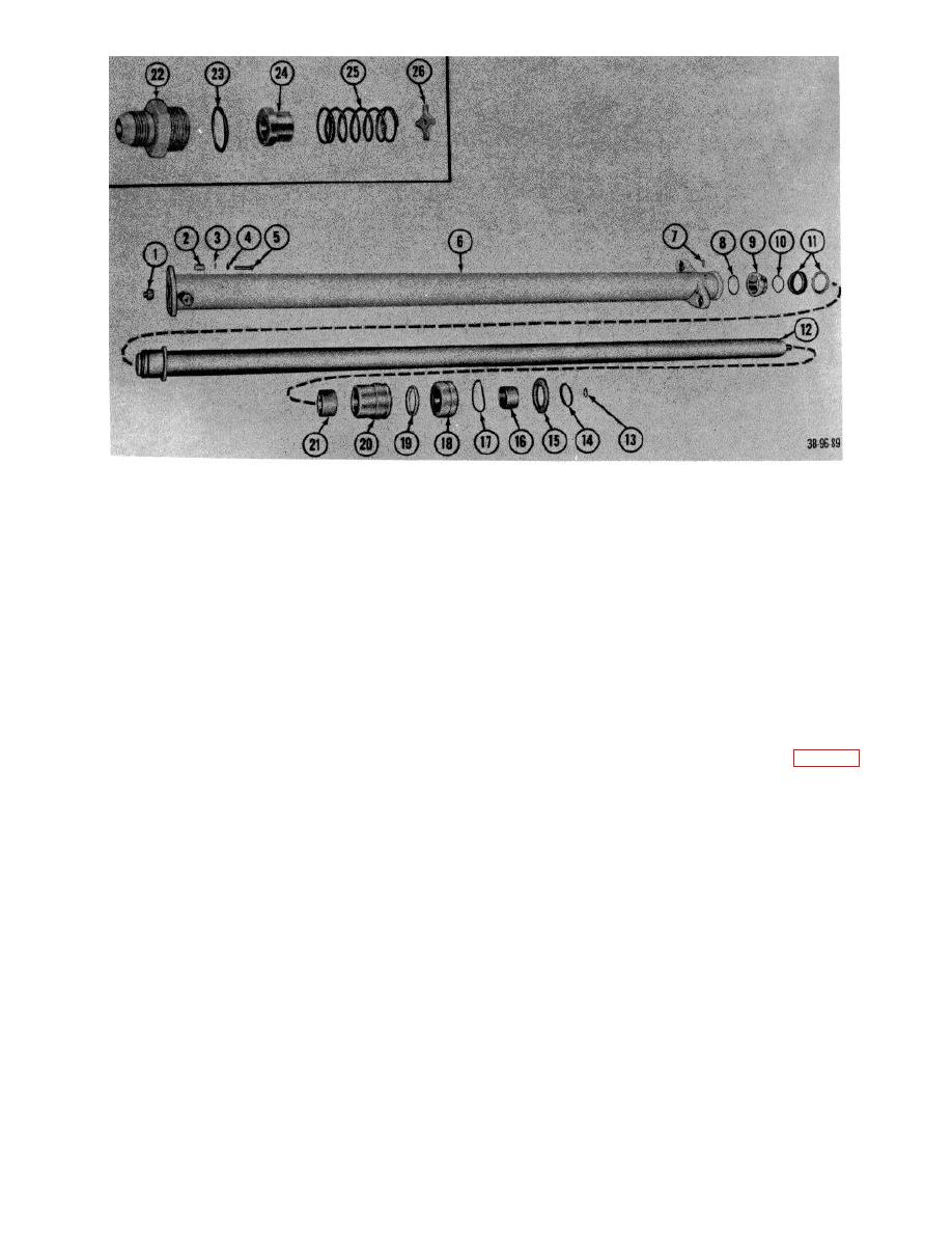 1
Pin, fulcrum
14
Ring, wiper, head washer
2
Spacer
15
Washer, threaded, cylinder head
3
Washer
16
Bushing, rod guide, upper
4
Lockwasher
17
Packing, preformed
5
Screw
18
Gland, packing, piston rod
6
Housing
19
Seal
7
Screw
20
Spacer
8
Ring, retaining
21
Bushing, rod guide, lower
9
Piston half
22
Adapter, pipe-to-tub
10
Packing, preformed
23
Packing. preformed
11
Packing
24
Spear
12
Plungers (piston rod)
26
Spring
13
Ring, retaining
26
Washer, special
Figure 101. Hoist cylinder, exploded view.
(2) Remove retaining ring (9, fig. 102) and
68. Fork Carriage
remove shim (8), load roller (7), and shim
(6).
a. Removal
(3) Remove remaining roller.
(1) Remove forks.
(Refer to TM 10-3930-
222-20)
c. Inspection.
(2) Raise inner upright until space permit
(1) Inspect rollers for wear and out-- of-round.
removal of carriage from upright
(2) Inspect crank assembly for wear.
assembly.
(3) Block inner upright securely.
d. Assembly.
(4) Remove chains from carriage (par. 70).
(1) Reverse procedures in b above.
(5) With suitable lifting device, remove
(2) Reverse rollers if worn.
carriage from upright assembly.
e. Installation
Reverse
procedures
in a
b. Disassembly
above.
(1) Remove load fork lead screws (par. 69).
AGO 7010A
122
|
|
Privacy Statement - Press Release - Copyright Information. - Contact Us |
