 |
|||
|
|
|||
|
Page Title:
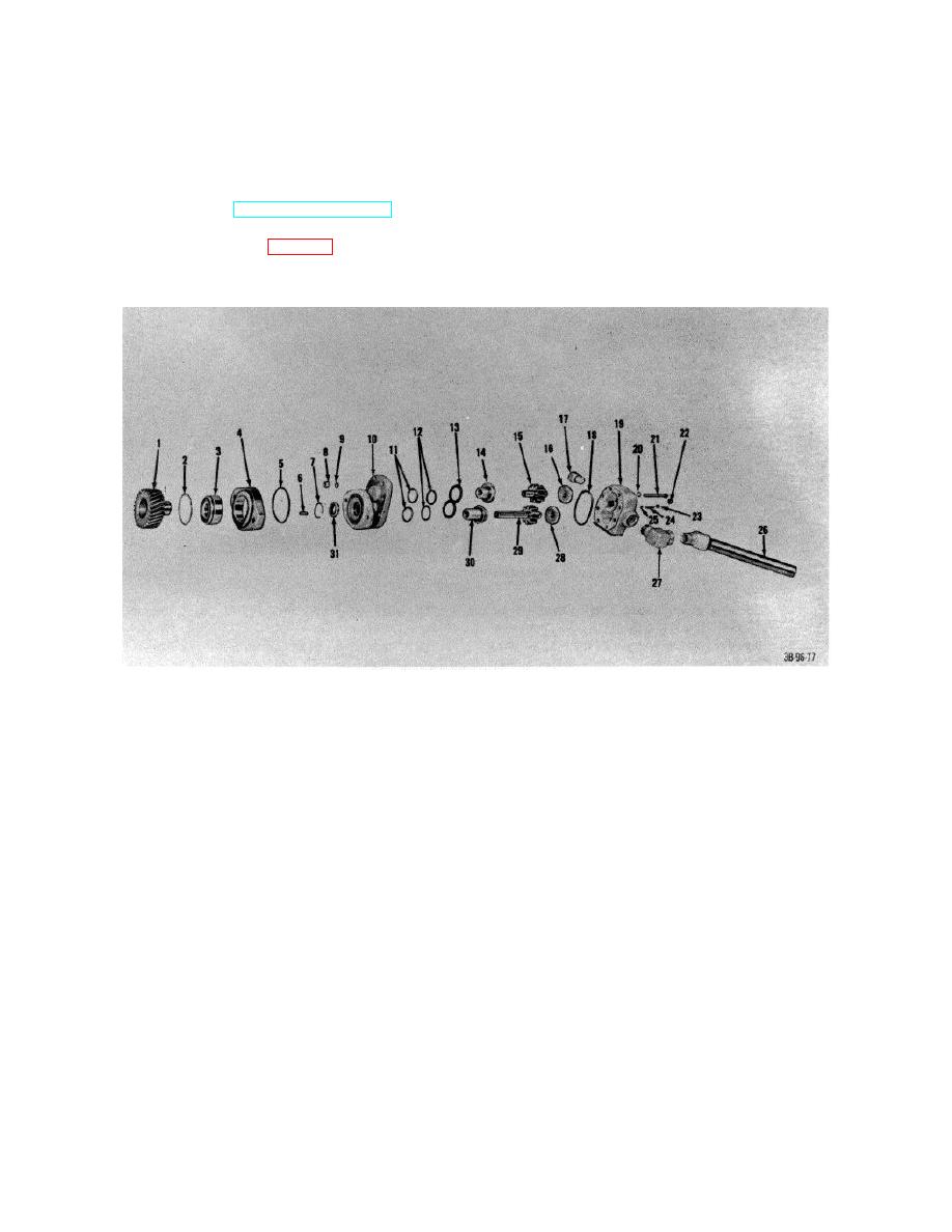
Figure 89. Steering hydraulic pump, exploded view. |
|
||
| ||||||||||
|
|
 (2) Push bearing , assembly (82) into shell
(3) Use new
gaskets and seals when
assembling pump.
until lockring (29) is , exposed.
(3) Remove lockring from shell.
e. Installation.
(4) Remove piston rod (65) from shell
(1) Reverse procedures in a above.
(5) Remove bearing (32) from piston rod (85).
(2) Aline pump drive gear hole with governor
(6) Remove backup ring (84) and packing (83)
drive dowell pin.
from bearing.
56. Steering Booster Cylinder
(7) Remove seal (30) and packing (31) from
a. Removal. Refer to TM 10-3930-222-20.
bearing.
b. Disassembly.
(8) Remove locknut (88) from piston rod.
(1) Remove crew (26, fig. 90) and lockwashers
(9) Remove piston (36) from piston rod.
(27) that secure end plate (28) to cylinder
(10) Remove rings (87) from piston (36).
shell (16) and remove plate.
1
Gear, hydraulic pump
17
Elbow
2
Ring, retaining
18
Seal, gasket
3
Bearing, ball
19
Body
4
Adapter, hydraulic pump
20
Washer
5
Packing, preformed
21
Screw
6
Key, woodruff
22
Plug, pipe
7
Ring, retaining
23
Plug, pipe
8
Nut
24
8pring
9
Washer
25
Ball
10
Cover
26
Elbow with pipe
11
Washer, backup
27
Elbow
12
Seals, ring
28
Bearing, body
13
8pring
29
Gear, drive
14
Cover, bearing
30
Cover, bearing
15
Gear, drive
31
Seal, shaft
16
Bering, body
Figure 89. Steering hydraulic pump, exploded view.
106
|
|
Privacy Statement - Press Release - Copyright Information. - Contact Us |
