 |
|||
|
|
|||
|
Page Title:
Figure 79. Differential assembly showing bearing caps. |
|
||
| ||||||||||
|
|
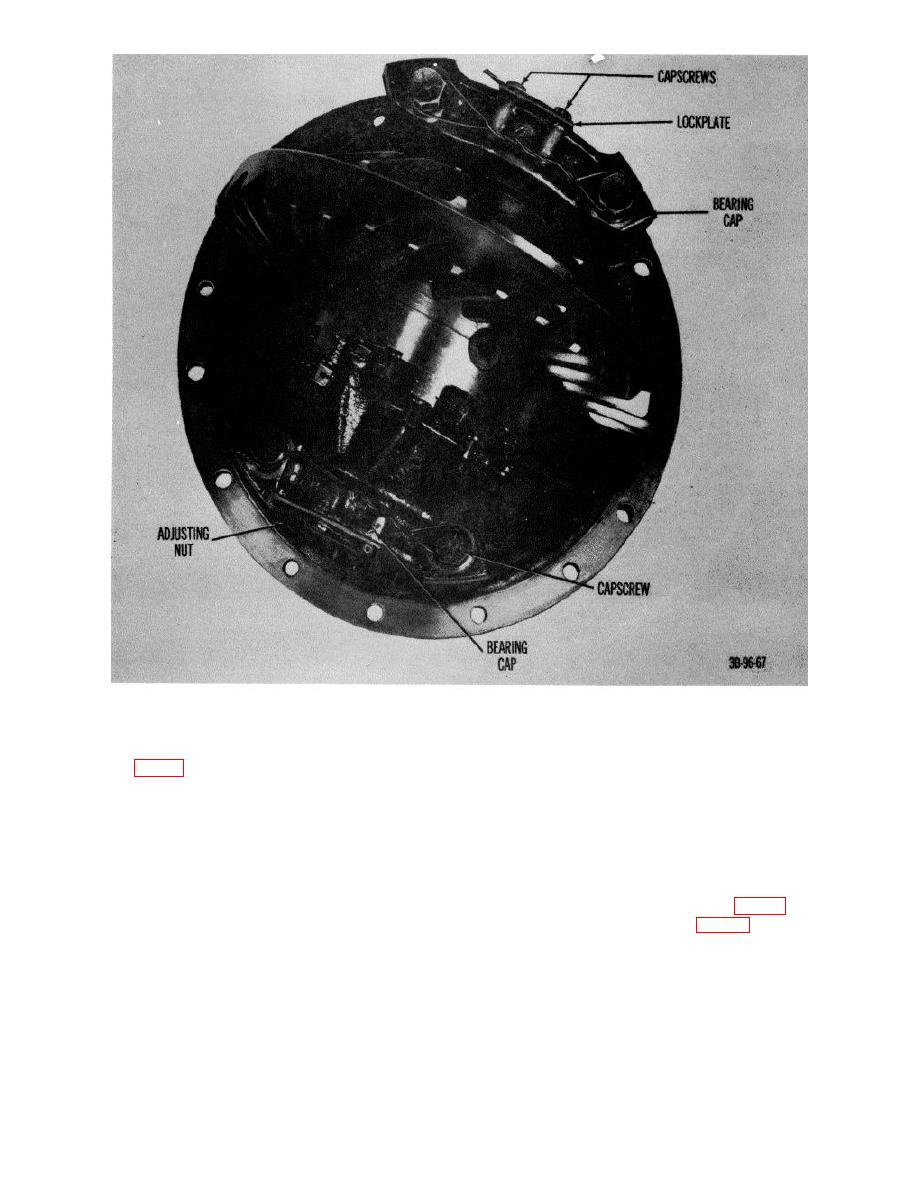 Figure 79. Differential assembly showing bearing caps.
(18) If new ring gear is to be installed, rivet ring gear
(23) Position side gear and washer on spider and
(12, fig. 81) to case half, using new rivets
pinion assembly.
(19) Lubricate differential case and all component
(24) Aline punch marks and position case halves
parts with GO-90.
together. Secure halves with 4 bolts (3) equally
(20) Position thrust washer (11) and side gear (10) in
spaced.
ring gear (12) and case half.
(25) Check assembly for free rotation of differential
(21) Place pinions (8) and thrust washers (9) on
spider (7) and then place spider assembly into
(26) Install remaining bolts (8 and 16) and torque to
ring gear and cam half (12).
96 to 106 foot-pounds.
(22) Install thrust washer (5) on side gear (6).
(27) Secure bolts with safety wire (fig. 80)
(28) Press bearing cone (2, fig. 81) on case (4) and
press bearing cone (18) on ring gear and came
half.
AGO 7010A
95
|
|
Privacy Statement - Press Release - Copyright Information. - Contact Us |
