 |
|||
|
|
|||
|
Page Title:
Figure 42. Clutch ring installed on front end housing assembly. |
|
||
| ||||||||||
|
|
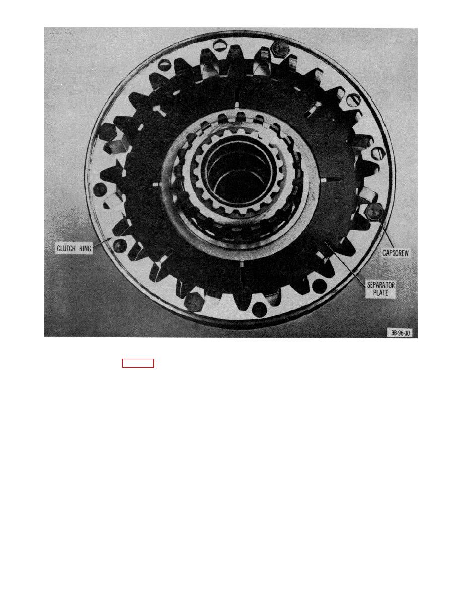 Figure 42.
Clutch ring installed on front end housing assembly.
(1) Remove bolts (15, fig. 71) and washers (16)
(7) Remove capscrews (26 and 28) and
that secure pump assembly (12) to converter
lockwashers (25 and 29) that secure adapter
housing (4) and remove pump.
plate (28) to housing and remove plate and
(2) Remove pump gasket (11), mounting plate (10),
gasket (22).
gasket (9), and packing (8) from housing.
(8) Remove spring (20) and ball (19) from housing.
(3) Remove retaining ring (7) from main shaft (1)
c.
Inspection. Inspect parts for wear, cracks, and
and drive the shaft from the housing.
breaks.
(4) Remove bearing (6) from housing.
d. Assembly.
Reverse procedures in b above
(5) Remove ring seal (2) from main shaft (1).
using new gaskets and new packing.
(6) Remove three screws (17) that secure baffle
Caution: Make certain that lugs on
plate (5) to housing (4) and remove plate.
torque converter fit into slots on
pump drive gear.
e. Installation. Reverse procedures in a above.
AGO 7100A
56
|
|
Privacy Statement - Press Release - Copyright Information. - Contact Us |
